Liquid crystal display panel and charging control method of liquid crystal display panel

A liquid crystal display panel, polarity control technology, applied to static indicators, instruments, etc., can solve the problems of insufficient positive polarity charging and negative polarity charging error, and achieve the effect of avoiding negative polarity charging error and improving positive polarity insufficient charging

Inactive Publication Date: 2020-08-04
SHENZHEN CHINA STAR OPTOELECTRONICS TECH CO LTD
View PDF6 Cites 2 Cited by
  • Summary
  • Abstract
  • Description
  • Claims
  • Application Information

AI Technical Summary

Problems solved by technology

[0003] The application provides a liquid crystal display panel, which solves the problems of insufficient positive polarity charging and wrong negative polarity charging that exist when the liquid crystal display panel is charged with polarity

Method used


Image

  • Liquid crystal display panel and charging control method of liquid crystal display panel
  • Liquid crystal display panel and charging control method of liquid crystal display panel
  • Liquid crystal display panel and charging control method of liquid crystal display panel

Examples


Embodiment Construction

[0021] The technical solutions in the embodiments of the present application will be clearly and completely described below in conjunction with the drawings in the embodiments of the present application. Apparently, the described embodiments are only some of the embodiments of this application, not all of them. Based on the embodiments in this application, all other embodiments obtained by those skilled in the art without making creative efforts belong to the scope of protection of this application.

[0022] In order to better understand the invention purpose of the present application, set forth as follows:

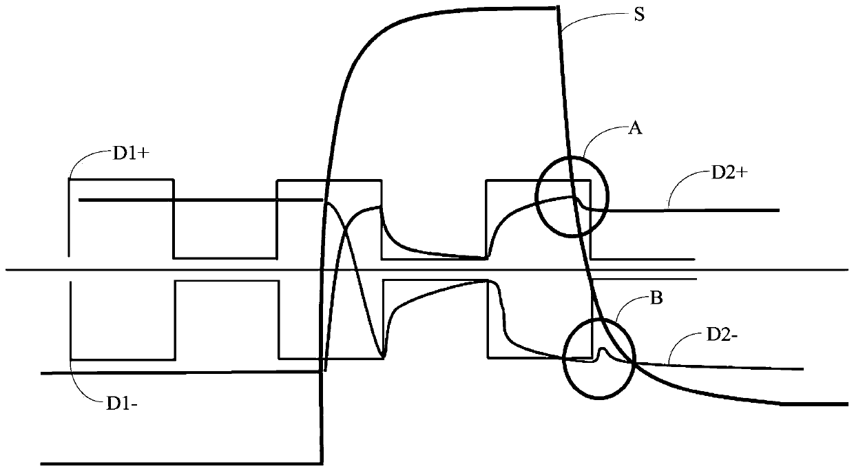
[0023] Such as figure 1 As shown, when the liquid crystal display panel is charged with polarity, the charging time of the theoretical curve D1+ of the positive polarity data signal and the theoretical curve D1- of the negative polarity data signal are the same, and the falling edge of the scanning signal S has a certain slope. When the polarity data signal D2+ is actu...


PUM


Abstract

The invention discloses a liquid crystal display panel. The liquid crystal display panel comprises pixel rows, scanning lines, a gate driver and a time sequence controller, different scanning signalsare adopted to carry out charging control on sub-pixels with different charging polarities in the same pixel row, positive polarity charging can be delayed to be turned off through scanning signals with rear phases, and the situation that positive polarity charging is insufficient is improved; the scanning signal with the front phase can turn off negative polarity charging in advance, and the problem of negative polarity charging errors is avoided.

Description

technical field [0001] The present application relates to the field of display technology, in particular to the field of liquid crystal display technology, and in particular to a liquid crystal display panel and a charging control method for the liquid crystal display panel. Background technique [0002] When the liquid crystal display panel is charged with a polarity, since the charging time of the positive polarity and the negative polarity are the same, and the falling edge of the scanning signal has a certain slope, when the positive polarity is charged, the charging stage has not yet ended, and the potential of the scanning signal has dropped. It is not enough to turn on the gate of the corresponding pixel, resulting in insufficient charging of the corresponding pixel; during negative charging, the charging phase has ended, and the potential of the scanning signal has not dropped to the gate off potential of the corresponding pixel, and the corresponding pixel can still ...

Claims


Application Information

Patent Timeline
Patent Type & Authority Applications(China)
IPC IPC(8): G09G3/36
CPCG09G3/3614
Inventor 高翔
Owner SHENZHEN CHINA STAR OPTOELECTRONICS TECH CO LTD
Why Eureka
Try Eureka