
Driving signal compensation method and device

A technology of driving signal and compensation method, applied in the direction of instruments, static indicators, etc., can solve the problems of incomplete shutdown, affecting the display effect, wrong charging, etc., to avoid charging errors and improve the display effect.

Active Publication Date: 2017-08-18
SHENZHEN CHINA STAR OPTOELECTRONICS SEMICON DISPLAY TECH CO LTD
View PDF8 Cites 2 Cited by
  • Summary
  • Abstract
  • Description
  • Claims
  • Application Information

AI Technical Summary

Problems solved by technology

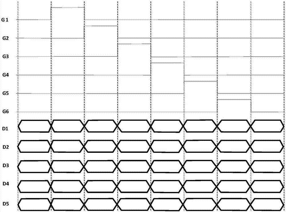
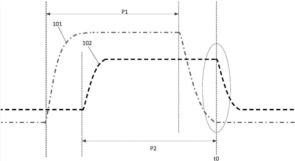
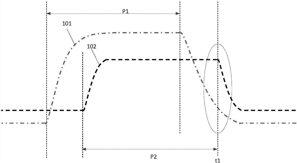
When the data signal is switched, that is, at time t1, the scanning signal is not low level (as shown by the dotted line box in the figure), that is, the TFT on the scanning line is not completely closed, thus causing the problem of wrong charging, which affects the display effect

Method used


Image

  • Driving signal compensation method and device
  • Driving signal compensation method and device
  • Driving signal compensation method and device

Examples


Embodiment Construction

[0038] The following descriptions of the various embodiments refer to the accompanying drawings to illustrate specific embodiments in which the present invention can be practiced. The directional terms mentioned in the present invention, such as "up", "down", "front", "back", "left", "right", "inside", "outside", "side", etc., are for reference only The orientation of the attached schema. Therefore, the directional terms used are used to illustrate and understand the present invention, but not to limit the present invention. In the figures, structurally similar units are denoted by the same reference numerals.

[0039] Please refer to Figure 4-6 , Figure 4 It is the waveform diagram of the scan signal and data signal before adjustment of a single pixel in the liquid crystal display panel.

[0040] The compensation method of the driving signal of the present invention includes:

[0041] S101. Acquire a first phase difference between an output scan signal and an output da...


PUM


Abstract

The invention discloses a driving signal compensation method and device. The driving signal compensation method comprises steps of obtaining a first phase difference between an output scanning signal and an output data signal of each pixel, performing regulation on the phase of the input scanning signal or the input data signal of a corresponding pixel according to a first phase difference in order to make the phase difference between the regulated output scanning signal and the corresponding output data signal of the pixel equal to the phase difference between the regulated input scanning signal and regulated the input data signal of the corresponding pixel. The driving signal compensation method and device avoid charging errors and improve a display effect.

Description

[0001] 【Technical field】 [0002] The invention relates to the technical field of displays, in particular to a compensation method and device for a driving signal. [0003] 【Background technique】 [0004] A liquid crystal display is currently the most widely used flat panel display, and is used in various electronic devices such as mobile phones, personal digital assistants (PDAs), digital cameras, computer screens or notebook computer screens. The liquid crystal display commonly used at present is usually composed of upper and lower substrates and a liquid crystal layer, and the substrate is composed of glass and electrodes. When electrodes are provided on the upper and lower substrates, displays in vertical electric field modes can be formed, such as TN (Twist Nematic) mode, VA (Vertical Alignment) mode, and MVA (Multi-domain Vertical Alignment) developed to solve the problem of narrow viewing angles. When electrodes are provided on only one side of the substrate, a display ...

Claims


Application Information

Patent Timeline
IPC IPC(8): G09G3/36
CPCG09G3/36G09G2310/0243
Inventor 郝思坤
Owner SHENZHEN CHINA STAR OPTOELECTRONICS SEMICON DISPLAY TECH CO LTD
Learn More