Power transmission mechanism for hybrid vehicle

A hybrid vehicle and power transmission technology, which is applied to hybrid vehicles, power units, pneumatic power units, etc., can solve problems such as difficulty in judging the normal driving state of hybrid vehicles.

Inactive Publication Date: 2011-05-18
AISIN AI CO LTD
View PDF1 Cites 7 Cited by
  • Summary
  • Abstract
  • Description
  • Claims
  • Application Information

AI Technical Summary

Problems solved by technology

However, it is difficult to judge whether a hybrid vehicle will continue to drive in a normal driving state in the future because the judgment is made on a case-by-case basis depending on road conditions and traffic conditions

Method used


Image

  • Power transmission mechanism for hybrid vehicle
  • Power transmission mechanism for hybrid vehicle
  • Power transmission mechanism for hybrid vehicle

Examples


no. 1 example

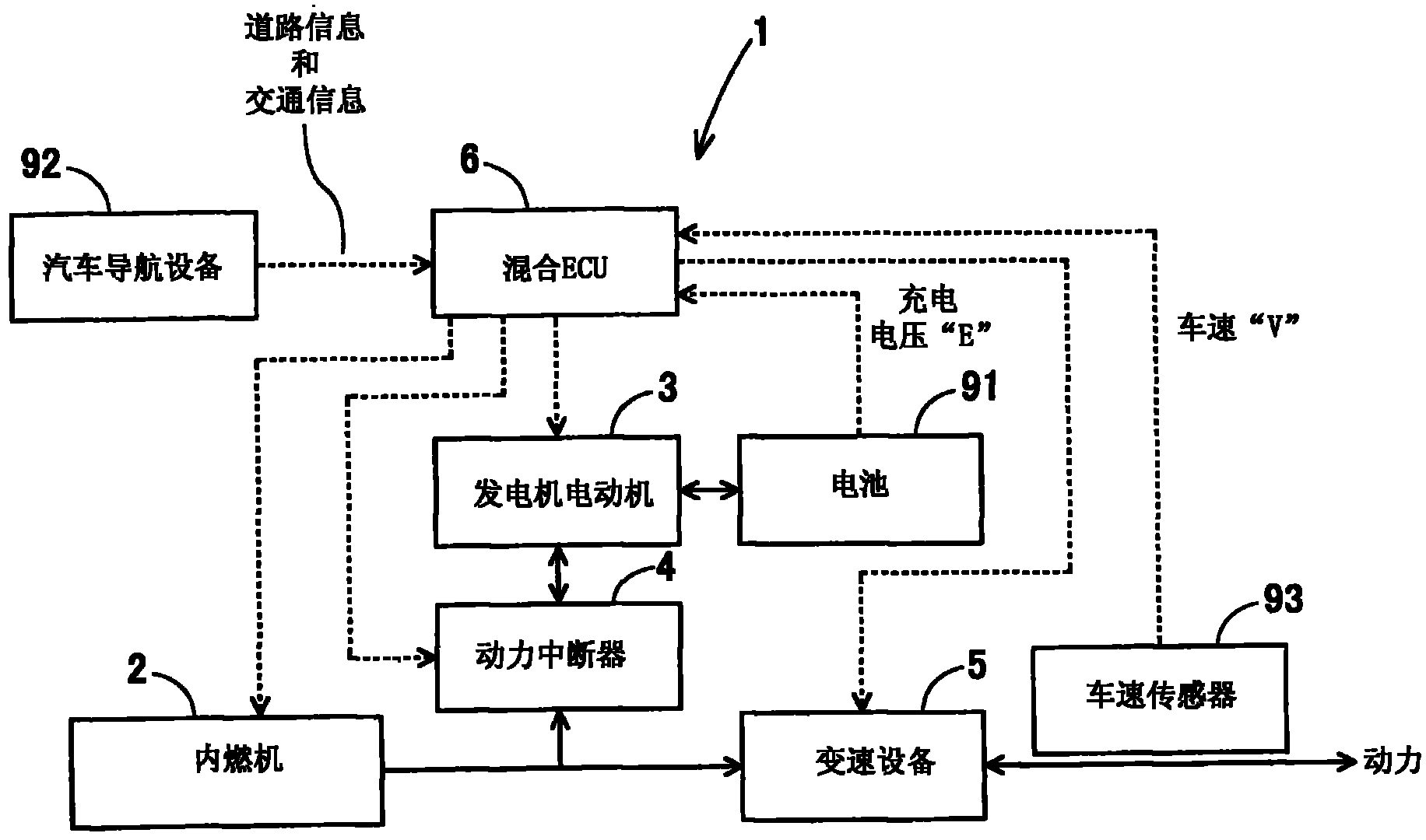
[0035] will refer to figure 1 and figure 2 One of the modes of execution of the present invention is described. For the power transmission device 1 of the hybrid vehicle according to the first embodiment of the present invention figure 1 The block diagram is shown. In the figures, arrows marked with solid lines represent power or energy flow, while arrows marked with dashed lines represent information or control flow. The power transmission apparatus 1 according to the first embodiment includes an internal combustion engine 2 , a generator motor 3 , a power interrupter 4 , a transmission device 5 and a hybrid ECU 6 .

[0036] The internal combustion engine 2 is a drive source for operating the hybrid vehicle, and outputs power from a crankshaft. The output power is input to the transmission device 5 through a clutch (not shown). The engine motor 3 has an output shaft coupled to a power transmission line through a power interrupter 4 . The engine motor 3 is connected to ...

no. 3 example

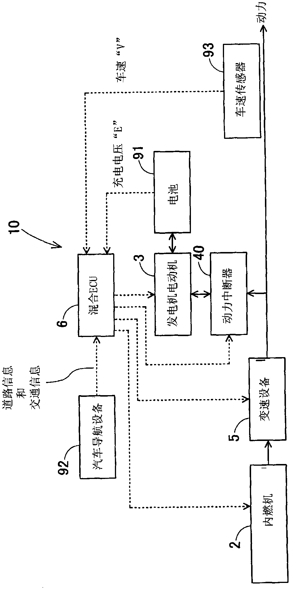
[0051] Below, will refer to image 3 and 4 Power transmission apparatuses for hybrid vehicles according to other embodiments of the present invention, ie, second and third embodiments, are described. The power transmission apparatuses according to the second and third embodiments differ from the above-described power transmission apparatus 1 according to the first embodiment in the arrangement of the power interrupter 4 in the hybrid vehicle. image 3 The block diagram of the power transmission device 10 according to the second embodiment is shown. Note that the power transmission device 10 according to the second embodiment includes the power interrupter 40 which is arranged on the side more downstream than the speed change device 5 . also, Figure 4 The block diagram of the power transmission device 11 according to the third embodiment is shown. Note that the power transmission device 11 according to the third embodiment includes two power interrupters 41 and 42 .

[00...


PUM


Abstract

A power switcher mechanism includes an internal combustion engine, a generator motor, a controller and a power interrupter. The internal combustion engine outputs a power. The generator motor carries out electric power generation as well as outputs a power when a power is input. The controller selects and then controls the internal combustion engine and the generator motor as a driving source for running. The power interrupter connects the generator motor with a power transmission route for transmitting the power and then disconnects the generator motor from the power transmission route, or vice versa, intermittently. The controller activates the power interrupter and then deactivates it, or vice versa, intermittently, with reference to information on road conditions, information on traffic conditions or information on vehicular conditions.

Description

[0001] cross reference [0002] The present application is based on Japanese Patent Application No. 2009-262,841 filed on Nov. 18, 2009, the entire contents of which are hereby incorporated by reference. technical field [0003] The present invention relates to a power transmission device for a hybrid vehicle having an internal combustion engine and a generator motor on the vehicle, the internal combustion engine and the generator motor being used as drive sources, respectively. Background technique [0004] Hybrid vehicles have entered practical applications. A hybrid vehicle has a dual drive source, ie, an internal combustion engine and a generator motor, and the hybrid vehicle intends to make use of the advantages of each of the internal combustion engine and the generator motor to realize improved fuel consumption, high output, and environmental protection. In such a hybrid vehicle, it is important to selectively control the drive source so that the generator motor driv...

Claims


Application Information

Patent Timeline
Patent Type & Authority Applications(China)
IPC IPC(8): B60K6/36B60W20/00B60W40/02B60L50/16B60W10/10
CPCY02T10/7044B60L2260/54B60L2240/68B60W10/06B60W2510/244B60K6/48B60W10/02Y02T10/6291Y02T10/7291Y02T10/7005Y02T90/162B60W2550/402Y02T90/16B60W20/00B60L11/1862B60L11/14B60W2550/20Y02T10/705Y02T10/7077B60W10/11B60W10/08Y02T10/6221B60L2240/62B60L3/04B60W50/0097B60L50/16B60L58/15B60W2554/00B60W2556/50Y02T10/62Y02T10/70Y02T10/7072Y02T10/72B60W20/12
Inventor 佐佐木环
Owner AISIN AI CO LTD
Why Eureka
Try Eureka