Power supply system, vehicle having power supply system, and control method of power supply system

Active Publication Date: 2009-10-22
TOYOTA JIDOSHA KK
View PDF25 Cites 27 Cited by
  • Summary
  • Abstract
  • Description
  • Claims
  • Application Information

AI Technical Summary

Benefits of technology

[0009]The present invention provides a power supply system which includes a plurality of storage devices to provide sufficient charging and discharg

Problems solved by technology

In this case, the power supply system as a whole is not able to provide the maximum charging characteristic or discharging characteristic after any one of the batteries reaches the charge or discharge limit.
Also, the boost/buck DC-DC converter is provided in each power stage of

Method used


Image

  • Power supply system, vehicle having power supply system, and control method of power supply system
  • Power supply system, vehicle having power supply system, and control method of power supply system
  • Power supply system, vehicle having power supply system, and control method of power supply system

Examples


Embodiment Construction

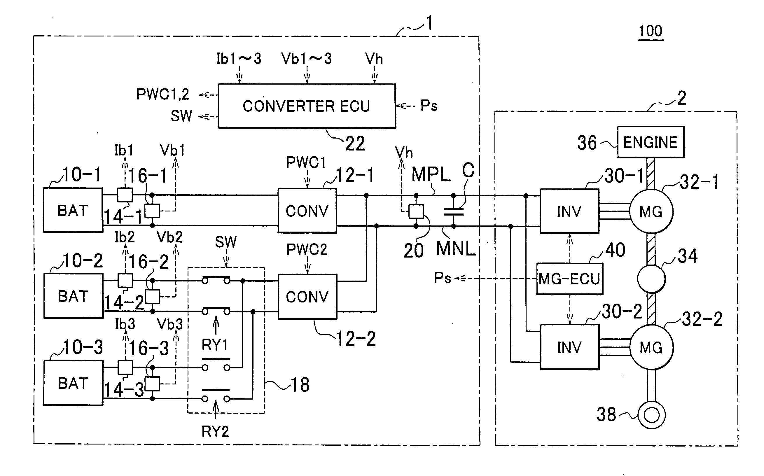
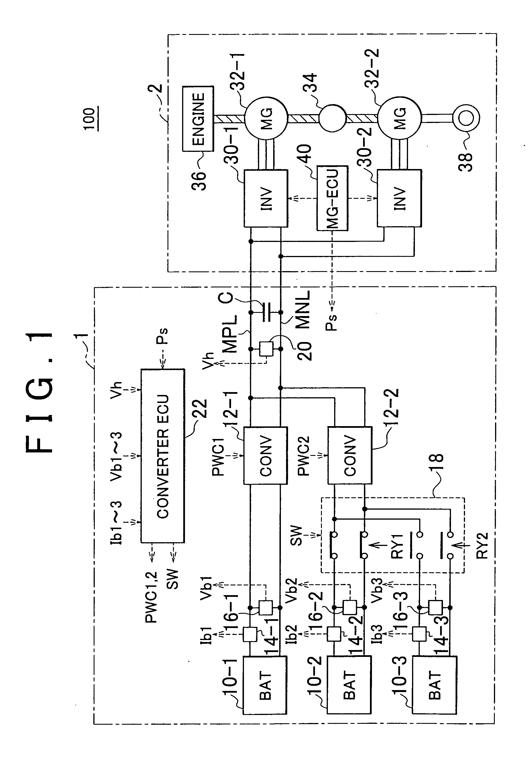
[0032]FIG. 1 is a general block diagram of a vehicle having a power supply system according to one embodiment of the invention. Referring to FIG. 1, the vehicle 100 includes a power supply system 1 and a driving force generating unit 2. The driving force generating unit 2 includes a first inverter 30-1, second inverter 30-2, first MG (motor-generator) 32-1, second MG 32-2, power divider 34, engine 36, driving wheels 38, and MG-ECU (electronic control unit) 40.

[0033]The first MG 32-1, second MG 32-2 and the engine 36 are coupled to the power divider 34. The vehicle 100 runs with driving force from at least one of the engine 36 and the second MG 32-2. Power generated by the engine 36 is split into two paths by the power divider 34. Namely, the power of the engine 36 is transmitted in part to the driving wheels 38 via one of the two paths, and is transmitted in part to the first MG 32-1 via the other path.

[0034]Each of the first MG 32-1 and the second MG 32-2 is an AC rotary electric m...


PUM


Abstract

A discharge distribution ratio calculating unit calculates a discharge distribution ratio, according to the ratio between an amount of electric power allowed to be discharged from a first storage device connected to a first converter, and the sum of amounts of electric power allowed to be discharged from second and third storage devices. A charge distribution ratio calculating unit calculates a charge distribution ratio, according to the ratio between an amount of electric power with which the first storage device is allowed to be charged, and an amount of electric power with which the storage device electrically connected to the second converter by a switching device is allowed to be charged. Then, the first and second converters are controlled according to the discharge distribution ratio in a discharge mode, or according to the charge distribution ratio in a charge mode.

Description

INCORPORATION BY REFERENCE[0001]The disclosure of Japanese Patent Application No. 2008-109334 filed on Apr. 18, 2008, including the specification, drawings and abstract, is incorporated herein by reference in its entirety.BACKGROUND OF THE INVENTION[0002]1. Field of the Invention[0003]The invention relates to charge and discharge control of a power supply system including a plurality of storage devices.[0004]2. Description of the Related Art[0005]Japanese Patent No. 3655277 discloses a power control system including a plurality of power stages. The power control system includes a plurality of power stages that are connected in parallel with each other and supply DC power to at least one inverter. Each of the power stages includes a battery and a boost / buck DC-DC converter.[0006]In the power control system, the above-indicated plurality of power stages are controlled so as to uniformly or evenly charge and discharge a plurality of batteries included in the respective power stages, so...

Claims


Application Information

Patent Timeline
IPC IPC(8): H02J7/34H02J7/00
CPCB60K1/02Y02T10/6239B60K6/445B60K6/547B60L11/1864B60L2240/421B60L2240/423B60W10/08B60W10/26B60W20/00B60W2510/244B60W2710/081B60W2710/083Y02T10/642Y02T10/7005Y02T10/7061B60K6/365B60L58/21Y02T10/62Y02T10/64Y02T10/70B60W20/13
Inventor KATO, NORIHIKO
Owner TOYOTA JIDOSHA KK
Why Eureka
Try Eureka