
Raised floor movable supporting base and raised floor

A support base and movable technology, which is applied to hull decks, ships, ship parts, etc., can solve problems such as failure to open and maintain normally

Inactive Publication Date: 2020-08-07
CSSC HUANGPU WENCHONG SHIPBUILDING COMPANY
View PDF6 Cites 4 Cited by
  • Summary
  • Abstract
  • Description
  • Claims
  • Application Information

AI Technical Summary

Problems solved by technology

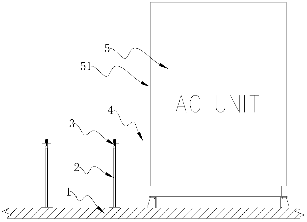
[0003] like figure 1 As shown, the air conditioner in the H6011 switchboard room is affected by the top cables and air ducts, etc. The air conditioner cannot be raised, that is, it cannot be placed on the raised floor, and can only be installed directly on the floor. The daily maintenance of the air conditioner requires opening the front panel , but the base of the raised floor in the prior art is welded together with the deck of the cabin, so the air conditioner will interfere with the raised floor of the cabin, and cannot be opened for inspection normally

Method used


Image

  • Raised floor movable supporting base and raised floor
  • Raised floor movable supporting base and raised floor
  • Raised floor movable supporting base and raised floor

Examples


Embodiment 1

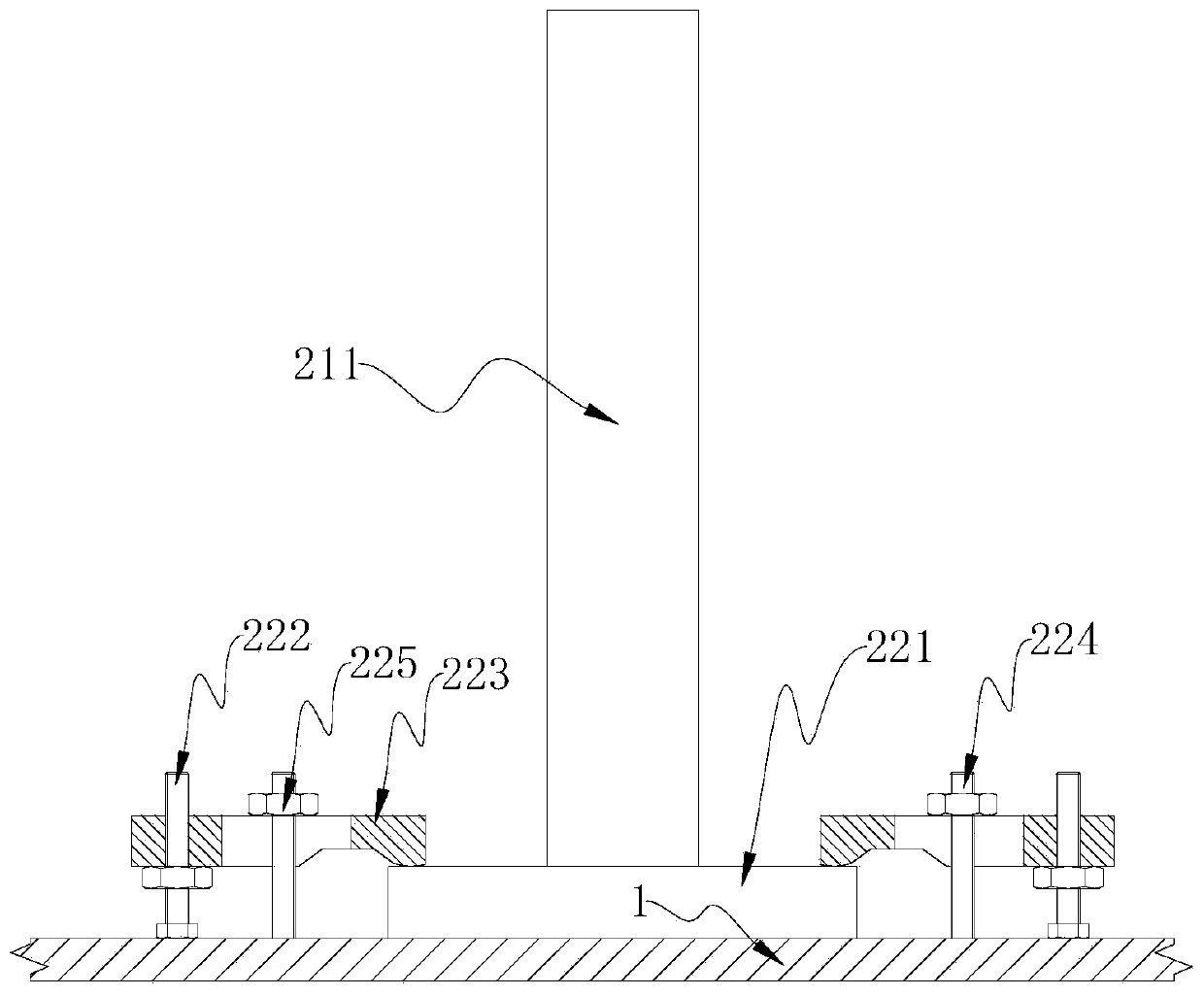
[0030] According to the first embodiment of the present disclosure, a raised floor movable support base is provided, including: a support body 211 and a detachable connection structure; the support body 211 is detachable from the cabin deck 1 through the detachable connection structure connect.

[0031] In this embodiment, the detachable connection structure is a clamping mechanism, such as figure 2 As shown, the detachable connection structure includes a first bottom plate 221, an adjusting bolt 222, a pressing plate 223, a compression stud 224 and a compression nut 225; The body 211 is welded and connected; according to the actual situation, a plurality of pressing plates 223 can be provided. In this embodiment, two pressing plates 223 are provided, and the two pressing plates 223 are respectively located on both sides of the supporting body 211, and each pressing plate 223 is away from one end of the supporting body 211 Adjusting bolts 222 are all threaded, and each press...

Embodiment 2

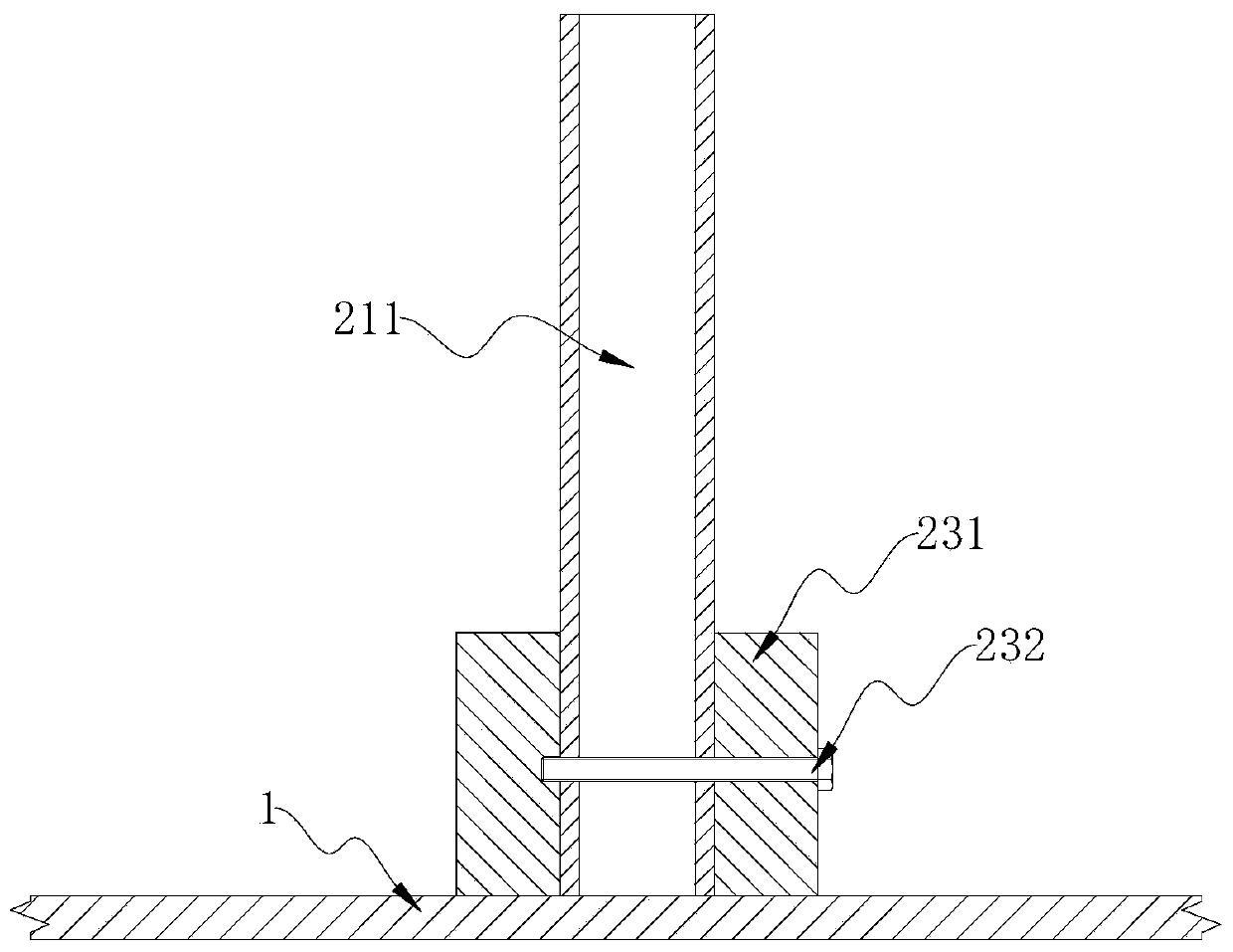
[0036] The main difference from Embodiment 1 of the raised floor movable support base is that in this embodiment, the detachable connection structure is realized by a mortise and tenon structure, specifically, as image 3 As shown, the detachable connection structure includes a second bottom plate 231 and an insertion rod 232; the second bottom plate 231 is welded on the cabin deck 1, and the surface of the second bottom plate 231 facing the side of the support body 211 is provided with a Mortise; one end of the support body 211 facing the cabin deck 1 is inserted into the mortise, and the insertion rod 232 passes through the second bottom plate 231 and the support body 211 in sequence.

[0037] working principle:

[0038] When installing, insert the support body 211 into the mortise, and then insert the insertion rod 232 into the second bottom plate 231 and the support body 211; .

[0039] The above has listed a specific embodiment of using the mortise and tenon structure t...

Embodiment 3

[0041] The main difference from Embodiment 1 of the raised floor movable support base is that in this embodiment, the detachable connection structure is a screw connection structure, specifically, as Figure 4 As shown, the detachable connection structure includes a third bottom plate 241, bolts 242 and a fourth bottom plate 243; the third bottom plate 241 is welded on one end of the support body 211 facing the cabin deck 1; the bolt 242 is penetrated on the third bottom plate 241; The bottom plate 243 is welded on the cabin deck 1 , and the fourth bottom plate 243 is provided with screw holes for threaded connection with the bolts 242 .


PUM


Abstract

The invention provides a raised floor movable supporting base and a raised floor with the same. The raised floor movable supporting base comprises a supporting body and a detachable connecting structure. The supporting body is detachably connected with a cabin deck through the detachable connecting structure. The detachable connecting structure comprises a flange, a stud and a nut; the flange is fixed to the end, facing a cabin deck, of the supporting body. One end of the stud is connected with a cabin deck, and the other end of the stud penetrates through the flange; the nut is located at theend, deviating from the deck of the cabin, of the flange and is in threaded connection with the stud. The detachable connecting structure is arranged between the supporting base and the cabin deck, when the air conditioner needs to be overhauled, the supporting base is detached from the cabin deck, the raised floor can be moved away, and therefore the front panel can be opened to maintain the airconditioner.

Description

technical field [0001] The disclosure relates to the technical field of ship decoration, in particular to a raised floor movable support base and a raised floor with the movable support base. Background technique [0002] The switchboard room and the wheelhouse on the ship are the cabins where the equipment is relatively concentrated and the cable laying area is the largest. In order to facilitate equipment wiring, installation and subsequent maintenance of cables, anti-static prefabricated raised floors are usually installed between switchboards and cabs, and sufficient space is reserved. [0003] Such as figure 1 As shown, the air conditioner in the H6011 switchboard room is affected by the top cables and air ducts, etc. The air conditioner cannot be raised, that is, it cannot be placed on the raised floor, and can only be installed directly on the floor. The daily maintenance of the air conditioner requires opening the front panel , but the base of the raised floor in t...

Claims


Application Information

Patent Timeline
IPC IPC(8): B63B3/48B63B15/00
CPCB63B3/48B63B15/00
Inventor 黄桂兰邓样熙梁涓华李小虎
Owner CSSC HUANGPU WENCHONG SHIPBUILDING COMPANY
Learn More