Air grate for raised floors

a technology of air grate and raised floor, which is applied in ventilation systems, lighting and heating apparatus, heating types, etc., can solve problems such as uneven floor surfaces, weight, and difficulty in solving them

Inactive Publication Date: 2008-11-06
OPSTOCK
View PDF50 Cites 32 Cited by
  • Summary
  • Abstract
  • Description
  • Claims
  • Application Information

AI Technical Summary

Benefits of technology

[0010]In still another aspect of the present invention, an air grate for a raised floor system includes a top plate with apertures for air flow through the top plate and for forming a part of a raised floor system, and a plurality of spaced-apart reinforcement ribs extending below the top plate for supporting weight on the top plate, with at least two of the ribs being parallel. The top plate includes corner-forming sections that extend outboard from the outmost ones of the reinforcement ribs. Leveling legs (also called “leveling screws”) operably engage the corner-forming sections for height adjustment. Foot-print-expanding brackets (also called “Z-brackets” herein) engage the leveling legs for extending the foot print of the leveling legs nearer to outer edges of the top plate so that the present air grate can be used on different raised floor systems without misalignment problems caused by different support stands.

Problems solved by technology

This problem is not easily solved, because air grates must rest on the same floor support as the raised floor panels.
In other words, the problem usually cannot be resolved simply by making the reinforcement ribs of an air grate deeper, because the deeper reinforcement ribs would interferingly engage the floor support, resulting in an uneven floor surface.
Further, the problem is not resolved simply by adding a large number of reinforcement ribs, since every rib adds expense, weight, and can adversely affect air flow.
Additional of a handle further aggravates the problem, because the air grate must include an open space for receiving the handle, which further reduces the weight-bearing strength of the air grate.

Method used


Image

  • Air grate for raised floors
  • Air grate for raised floors
  • Air grate for raised floors

Examples


Embodiment Construction

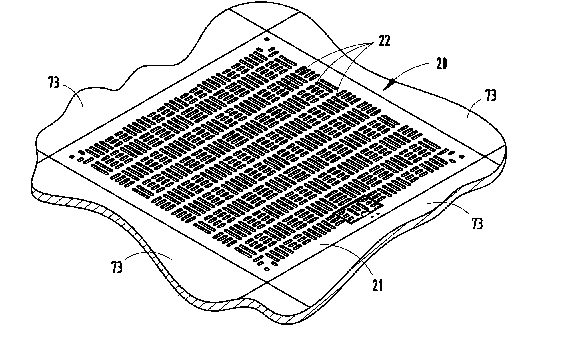
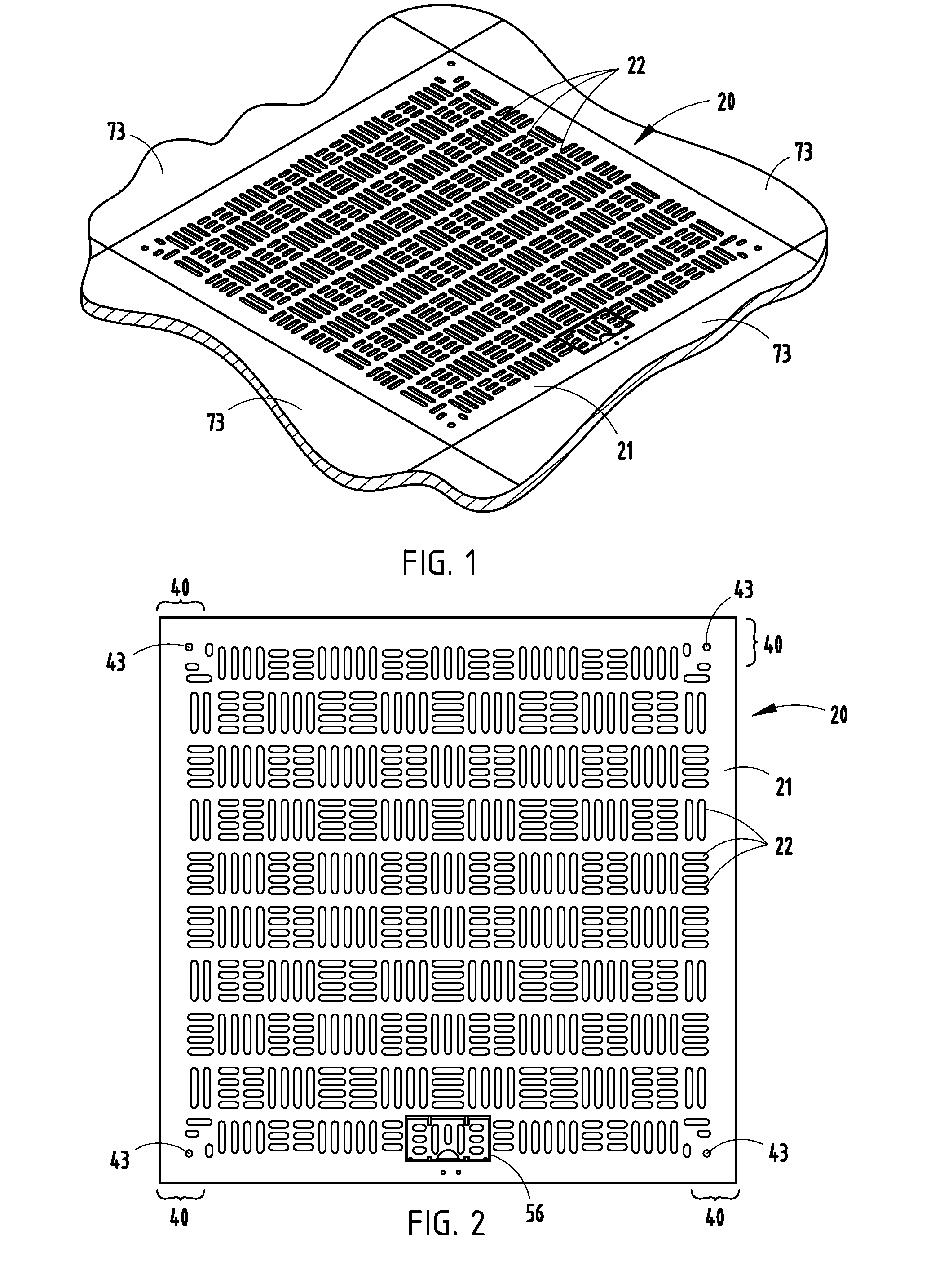
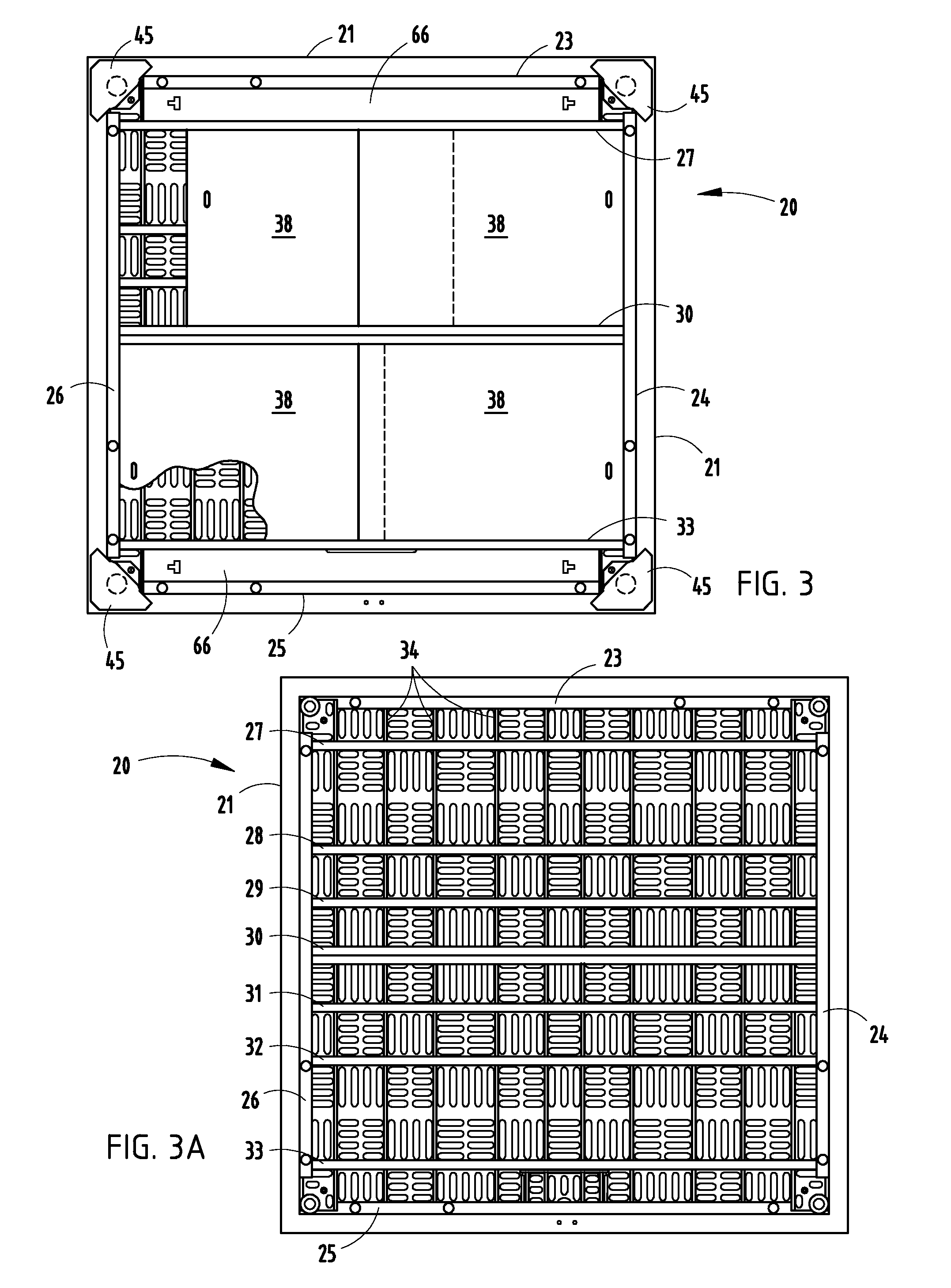
[0022]An air grate 20 (FIG. 1) is illustrated embodying the present invention. It is noted that specific dimensions are given to facilitate an understanding of the present invention, but that the present invention is not limited to only those dimension. The present air grate 20 is configured for use in a raised floor system as shown in FIG. 1, and includes a top plate 21 with apertures 22 for air flow, and includes a matrix of interconnected reinforcement ribs for structural support. Notably, the density of apertures 22 can be increased or decreased depending on the particular requirements of an installation. The illustrated apertures 22 provide up to about 50% open area for air flow. The illustrated ribs include perimeter ribs 23-26 (FIG. 6) of a first dimension D1 (approximately 2 inches high) welded to top plate 21, first parallel ribs 27-33 of a shorter second dimension D2 (about 1½ inches high) welded to top plate 21, and shorter second transverse parallel ribs 34 of a third di...


PUM


Abstract

An air grate for a raised floor includes a top plate with apertures for air flow, and reinforcement ribs for structural support. Pairs of ribs include edge flanges that define a horizontal track. Two flat dampener panels temporarily flex to slip between the edge flanges for assembly and then unflex for adjustable movement along the track between different overlapping positions for controlled air flow. The top plate includes corner-forming sections and leveling legs for height adjustment. Foot-print-expanding brackets engage the leveling legs for extending their foot print outwardly so that the air grate can be used on different raised floor systems without misalignment problems with stanchion supports. A handle is pivotally mounted in the top plate between a flush position and a raised position for grasping to lift the air grate, the handle having apertures matching the pattern of the top plate.

Description

BACKGROUND[0001]The present invention relates to an air grate for a raised floor system such as for a computer room, the air grate being configured for adjustable dampened air flow.[0002]Raised floor systems allow flexible installation and distribution of cabling and wires, and also allow air conditioning to be funneled under the floor and into the room through apertured panels (also called “air grates”) at selected strategic locations in the room. However, improvements are desired in these floor systems to allow adjustable control of air flow through the raised floor systems without substantial increase in manufacturing cost. Further, improvement is desired so that a particular apertured panel can be used to mate with a wide variety of existing raised floor panel systems. Still further, improvement is desired to provide an air grate with flush handle, where the apertured panel and handle are sufficiently sturdy to support substantial weight, yet where the handle is not a trip hazar...

Claims


Application Information

Patent Timeline
Patent Type & Authority Applications(United States)
IPC IPC(8): F24F13/00
CPCF24F13/082F24F2221/40Y10T292/108
Inventor DEJONGE, MARK O.CLIFFORD, JAMES F.
Owner OPSTOCK
Why Eureka
Try Eureka