Raised flooring system and method

a flooring system and raised technology, applied in the field of raised flooring system and method, can solve the problems of increasing power requirements, affecting the interconnection of electrical power distribution and cabling systems, and often landlords are forced to solve, etc., to achieve the effect of enhancing interconnection

Inactive Publication Date: 2005-02-22
OWEN DAVID D
View PDF29 Cites 40 Cited by
  • Summary
  • Abstract
  • Description
  • Claims
  • Application Information

AI Technical Summary

Benefits of technology

The present invention is directed to an improved plastic pedestal to supplant the pedestal of FIG. 17 of The Improvement Patent. The improved pedestal provides enhanced interconnection both between the pedestal and base flooring panels under the pedestal and working floor panels atop the pedestal. In addition the improved pedestal provides the option of working floor leveling where desired.

Problems solved by technology

Now, due to the changes in market economies, frequently landlords are forced to solve problems of substantial increases in power requirements, additional cooling and cable distribution.
Modern day office requirements have placed burdens on heating / cooling, electrical power distribution and cabling systems which were never anticipated when even the most modern office buildings were built.
Physical concentrations of PCs and other electrical enhancements such as facsimile machines, copiers, printers, scanners, and in particular, the personnel operating the equipment, have placed extra-ordinary burdens on the most sophisticated and powerful heating, ventilating and air conditioning systems.
These concentrations of equipment and personnel generated heat are most frequently offset by increasing the velocity of chilled air from overhead diffusers, usually at the expense of other areas, and to the discomfort of personnel.
Convenient, horizontal retro-feeding of electrical power wiring or cabling through finished stud and dry wall partitions is particularly difficult, costly, disruptive and sometimes, impossible unless sufficient conduit has been pre-installed.
This plenum approach has severe difficulties and limitations.
Once additional power is in place, an undesirable result is a comparable increase in generated heat, requiring more cooling.
Typically such additional heat loads have not been anticipated nor dealt with in the base building design or construction.
Increases in air velocities result in increased noise levels and are really nothing more than cycling air more rapidly through the base system which has a finite heat absorbing capacity.
In the event of such a fire, the egress of the supplemental conditioning air from the plenum would obviously be undesirable.
Prior proposals for supplemental flooring systems have all been excessively complex such that they required skilled installers for disproportionately long periods of time.
Further, prior proposed systems have not been fully modular and had inadequate provision for access to service lines extending through such a system.

Method used


Image

  • Raised flooring system and method
  • Raised flooring system and method
  • Raised flooring system and method

Examples


Embodiment Construction

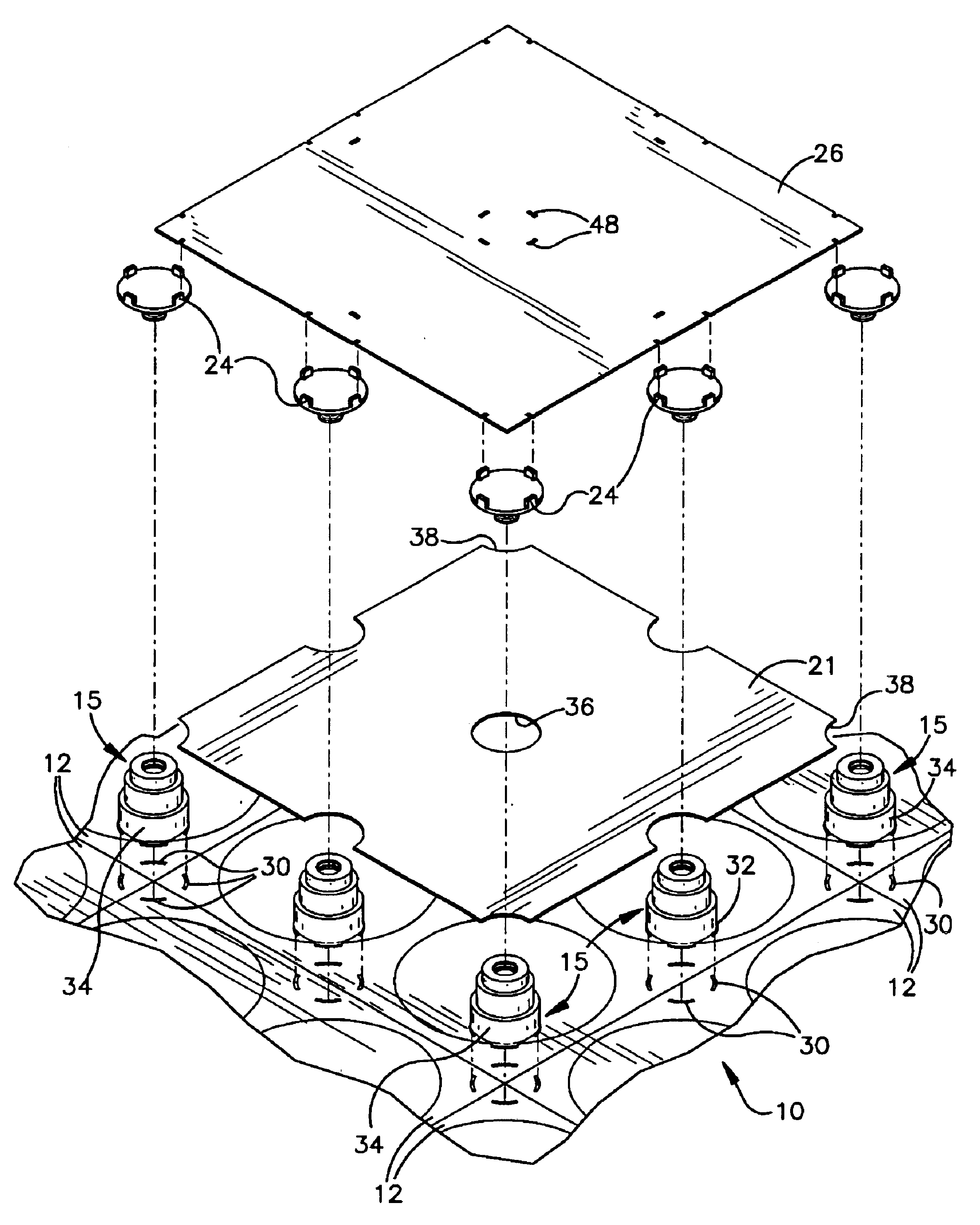
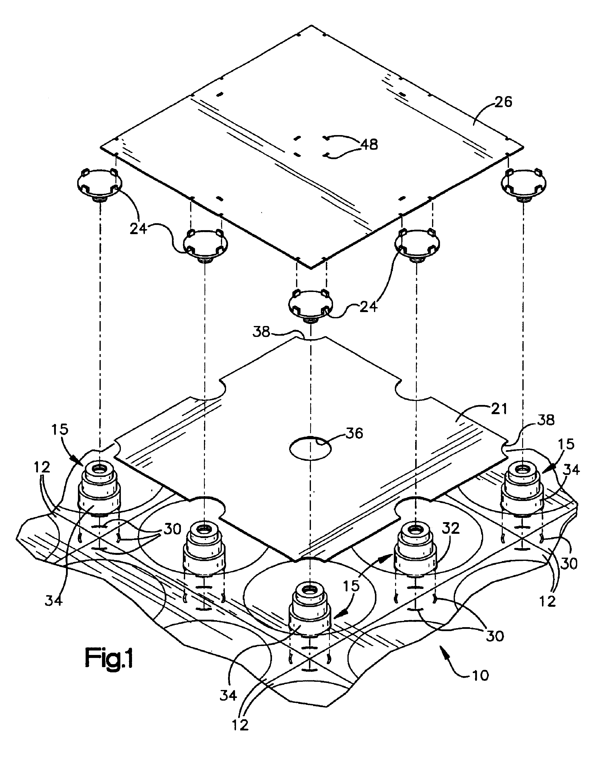
Referring to the drawings and to FIG. 1 in particular, a fragmentary portion of an assembled flooring system utilizing plastic components is shown generally at 10. A plurality of base panels 12 are provided. Each base panel has four relatively large through apertures 14 which are provided to minimize weight and material consumed.

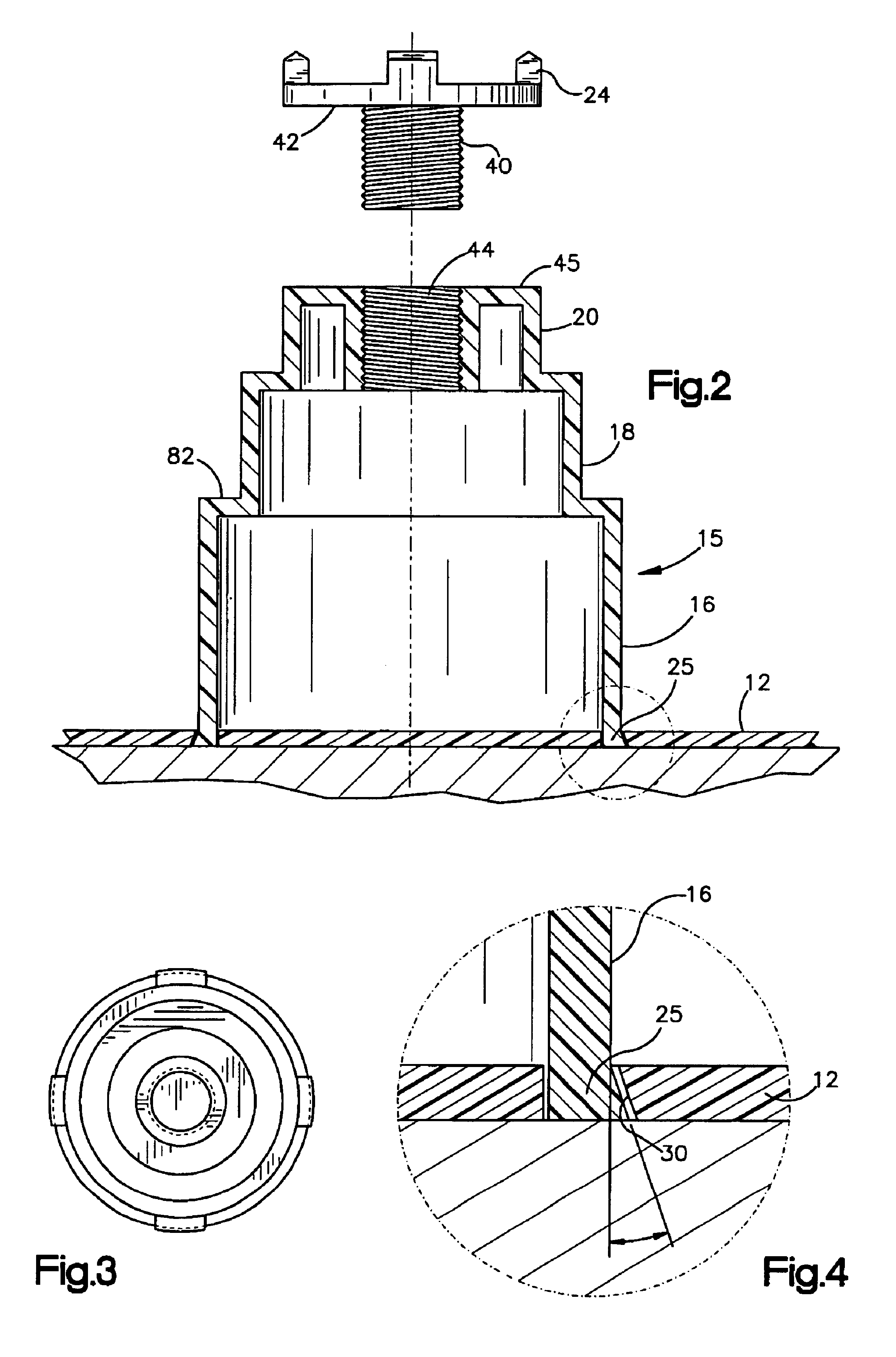
A plurality of pedestals 15 are provided. The pedestals include base, central and top conical segments 16,18,20. The conical segments are axially aligned and contiguous to define support surfaces for panels. More specifically an annular surface 22 which is flat and horizontal when in use interconnects the base and central segments for support of cable floor panels 16. Similarly, a flat annular surface 24 interconnects the central and top segments 18,20 for support of communication panels(not shown). Pedestal caps 24 rest atop the pedestals to provide flat top surfaces 25 which function as support surfaces for work floor panels 26.

Each pedestal 15 includes fo...


PUM


Abstract

An improved pedestal for a flooring system of the type which utilizes prefabricated base panels installed in side by side relationship to support a series of upstanding pedestals positioned in a geometric pedestal array is disclosed. The pedestals support further panels which define chases. Working floor panels are mounted atop caps which form tops of the pedestals. In one embodiment the caps each thread into a threaded bore in a pedestal body for leveling adjustments. Novel feet project downwardly from the pedestal bodies to provide positive locks with the base panels.

Description

This invention relates to an accessible raised floor system for use in office buildings or the like.BACKGROUND OF THE INVENTIONHistorically, building owners have not had to deal with tenant requirements for supplemental cooling, power and cabling, with the exception of special purpose computer or trading rooms. These special purpose rooms have been dealt with almost as if they were separate structures. Unless a building was occupant owned, a tenant had to deal with these requirements. Now, due to the changes in market economies, frequently landlords are forced to solve problems of substantial increases in power requirements, additional cooling and cable distribution.As the use of office space has evolved since the development of personal computers (PC), there has been an escalation in the need for and frequency of re-organization and re-configuration of office space. Enormous amounts of effort and study have gone into the planning and design of office space in order to render its us...

Claims


Application Information

Patent Timeline
Patent Type & Authority Patents(United States)
IPC IPC(8): E04F15/024
CPCE04F15/0247E04F15/02452
Inventor OWEN, DAVID D.
Owner OWEN DAVID D
Why Eureka
Try Eureka