Low-scattering carrier considering horizontal polarization and vertical polarization and testing method of low-scattering carrier

A vertical polarization and low-scattering technology, which is applied in the measurement of scattering characteristics, etc., can solve the problem that the low-scattering carrier cannot take into account the horizontal polarization and vertical polarization.

Active Publication Date: 2020-08-07
CHENGDU AIRCRAFT INDUSTRY GROUP
View PDF13 Cites 17 Cited by
  • Summary
  • Abstract
  • Description
  • Claims
  • Application Information

AI Technical Summary

Problems solved by technology

[0007] The object of the present invention is to provide a low-scattering carrier with both horizontal and vertical polarization and its test method. And the test method proposed later based on the low-scattering carrier can be directly applied to the low-scattering carrier, which solves the problem that the existing low-scattering carrier cannot take into account the horizontal polarization and the vertical polarization.

Method used


Image

  • Low-scattering carrier considering horizontal polarization and vertical polarization and testing method of low-scattering carrier
  • Low-scattering carrier considering horizontal polarization and vertical polarization and testing method of low-scattering carrier
  • Low-scattering carrier considering horizontal polarization and vertical polarization and testing method of low-scattering carrier

Examples


Embodiment 1

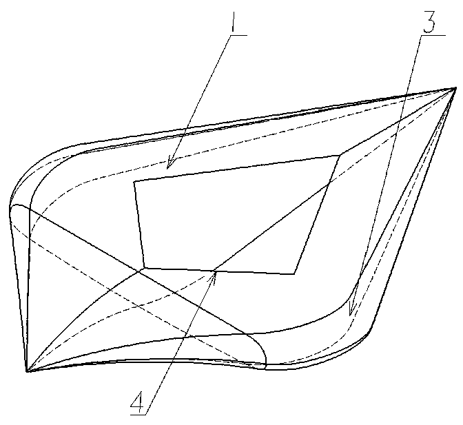
[0062] A low-scattering carrier that takes into account both horizontal and vertical polarization, such as Figure 2-Figure 9 , including a carrier, the carrier is composed of an upper curved surface 1, a lower curved surface 2 and a transition curved surface 3, the carrier is a metal hollow structure, in the shape of a water drop, and the left and right axes are symmetrical

[0063] The sharper end at both ends of the carrier is the head, and the other end is the tail, and the upper curved surface 1 of the carrier near the head is a plane, such as figure 2 , 3 , 4, 6, 9, the tail of the carrier is bent downward;

[0064] Such as Figure 8 , 10 , the carrier satisfies

[0065] Forward sharp angle θ f ≤180°-2(α+Δ) (1)

[0066] Rear sharp angle θ e ≥2(α+Δ) (2)

[0067] Such as Figure 10 , where α is the angle of the forward focus angle domain, Δ is the margin from the forward focus angle domain, and the angle units of the angles α and Δ in the formula are degrees.

...

Embodiment 2

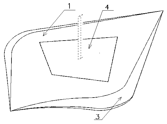
[0072] The present invention is on the basis of above-mentioned embodiment 1, as image 3 , the plane part of the upper curved surface 1 is recessed with a flange interface 4, the flange interface 4 is lower than the plane part of the upper curved surface 1, and after the mounting seat of the test target is installed on the flange interface 4, the test target The upper surface of the mount is flush with the flat part of the upper curved surface 1, such as Figure 4 , the edge of the cover plate should be parallel to the edge of the carrier such as Figure 5 As shown, the peaks of the traveling wave formed by the edge of the cover plate and the edge of the carrier coincide when the electromagnetic wave is vertically polarized incident.

[0073] In order to better realize this solution, further, the angle α of the forward focus angle domain is 45°, the margin Δ from the forward focus angle domain ranges from 5° to 10°, and the surface roughness of the carrier Ra≤ 1.6.

[0074...

Embodiment 3

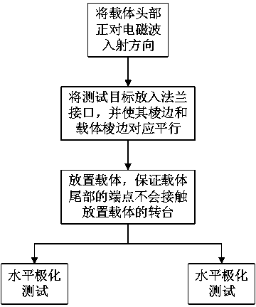
[0079] A test method for low-scattering carriers that takes into account both horizontal and vertical polarization, such as figure 1 , testing a low-scattering carrier with both horizontal and vertical polarization described in the above-mentioned embodiment 1 or embodiment 2, including the following steps carried out in sequence:

[0080] First install before testing:

[0081] Step S1: Face the head of the carrier to the incident direction of the electromagnetic wave, such as Figure 10 shown;

[0082] Step S2: Put the test target to be tested into the flange interface 4 on the upper curved surface 1 of the carrier, and make the edge of the test target cover plate parallel to the edge of the carrier, such as Figure 5 , so that the traveling wave peaks formed by the edge of the cover plate and the edge of the carrier coincide when the electromagnetic wave is incident on vertical polarization;

[0083] Step S3: After installing the test target, check to ensure that when the...


PUM

PropertyMeasurementUnit
lengthaaaaaaaaaa
widthaaaaaaaaaa
sizeaaaaaaaaaa

Abstract

The invention provides a low-scattering carrier considering horizontal polarization and vertical polarization and a testing method of the low-scattering carrier and belongs to the field of electromagnetic scattering measurement. The low-scattering carrier comprises a carrier body; the carrier body is composed of an upper curved surface, a lower curved surface and a transition curved surface; the carrier body is of a metal hollow structure, is droplet-shaped and is in bilateral symmetry; the sharp end of the two ends of the carrier body are the head, the other end of the carrier body are the tail; and the upper curved surface 1, close to the head, of the carrier body is a flat plane; the tail of the carrier body bends downwards; the forward sharp corner and backward sharp corner of the carrier body meet a certain limitation; due to the special structural limitation of the carrier body, horizontal polarization and vertical polarization can be considered at the same time; the testing method based on the low-scattering carrier can be directly applied to the low-scattering carrier; and the problem that horizontal polarization and vertical polarization cannot be well considered in an existing low-scattering carrier is solved.

Description

technical field [0001] The invention relates to the field of electromagnetic scattering measurement, in particular to a low-scattering carrier with both horizontal and vertical polarization and a testing method thereof. Background technique [0002] In the development process of stealth aircraft, a large number of design RCS (Radar Cross Section, radar cross section) tests are required to select parameters and verify simulation calculation results. The size of the stealth part of the aircraft is generally between 1 and 5m. If it is directly used for RCS testing, on the one hand, it cannot be implemented because the size is larger than the size of the quiet zone of the general darkroom. On the other hand, the RCS of the part may be larger than the pre-test materials, details or The RCS of the antenna, thus causing the RCS of the pre-tested material or details to be buried in the RCS of the component; The structure is completely exposed, introducing a new source of scattering...

Claims


Application Information

Patent Timeline
Patent Type & Authority Applications(China)
IPC IPC(8): G01N21/47
CPCG01N21/47
Inventor 梁爽李景虎张斌聂暾徐伊达周萍滕杰
Owner CHENGDU AIRCRAFT INDUSTRY GROUP
Why Eureka
Try Eureka