Camera module and electronic equipment

A camera module and electronic equipment technology, applied in the field of electronics, can solve the problem that the functional requirements of the breathing lamp and the screen ratio requirements cannot be taken into account, affecting the user experience, etc., so as to achieve the consideration of the amount of light output, avoid the weakening of the light, and achieve high-quality imaging quality. Effect

Pending Publication Date: 2020-08-07
昆山丘钛光电科技有限公司
View PDF0 Cites 1 Cited by
  • Summary
  • Abstract
  • Description
  • Claims
  • Application Information

AI Technical Summary

Problems solved by technology

However, this solution is at the cost of sacrificing functions. Although it improves the screen ratio, it affects the user experience.
[0004] It can be seen that there are currently technical problems that the functional requirements such as breathing lights and the screen-to-body ratio cannot be balanced

Method used


Image

  • Camera module and electronic equipment
  • Camera module and electronic equipment
  • Camera module and electronic equipment

Examples


Embodiment 1

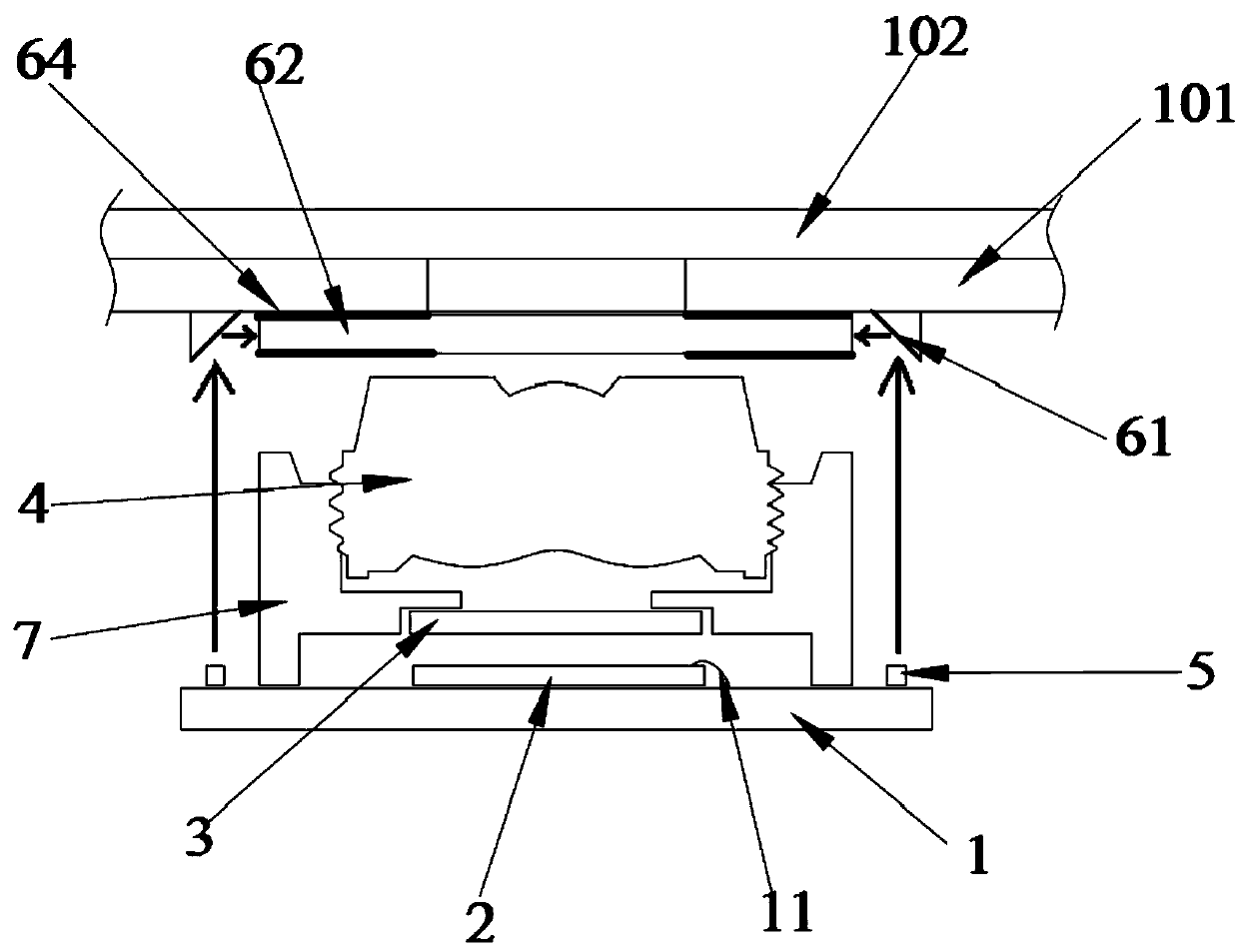
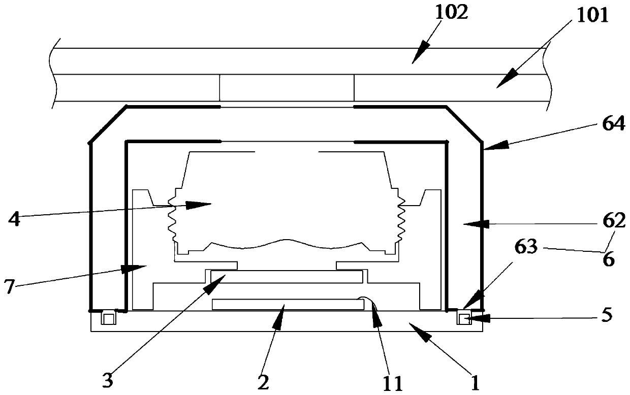
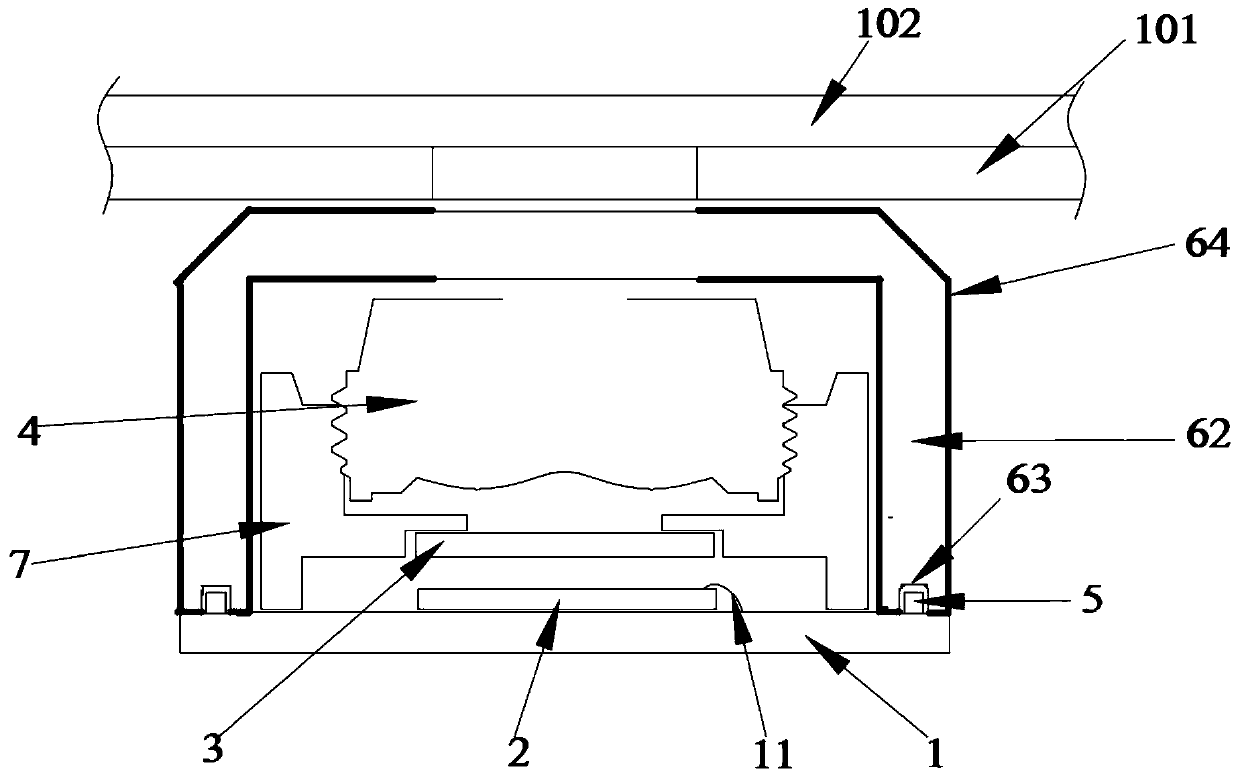
[0030] In this embodiment, a camera module is provided, such as Figure 1-5 shown, including:

[0031] An imaging section and a light emitting section, wherein the imaging section includes a circuit substrate 1, a photosensitive element 2 and a lens 4, and the light emitting section includes a light emitting element 5 and a light guide structure 6;

[0032] Wherein, the light-emitting element 5 is fixed on the outer surface of the imaging part, and the light emitted by the light-emitting element 5 is guided by the light guide structure, and is emitted out of the camera module from the direction facing the front of the lens 4, so as to realize the connection with the camera module. The optical path of the photosensitive element 2 to obtain light basically overlaps, so that after the camera module is installed in the electronic device, the light emitting element 5 and the photosensitive element 2 can emit and obtain light through the same transparent hole. In addition, there is...

Embodiment 2

[0063] like Image 6 As shown, this embodiment provides an electronic device, including the camera module 601 described in the first embodiment.

[0064] In a specific implementation process, the electronic device may be a mobile phone, a tablet computer, a tester, or a smart watch, etc., which are not limited here and will not be listed one by one.

[0065] In a specific implementation process, the electronic device may include a screen 101, the camera module 601 is located under the screen 101, and the outer surface of the screen 101 may also be provided with a protective layer 102 (for example, a glass layer). The light emitting element 5 in the electronic device may be a light source for realizing the function of a breathing light. Through the built-in camera module 601 provided by Embodiment 1, which has both light-emitting element 5 and photosensitive element 2, the breathing light function or other light-emitting functions of the electronic device can share the same tr...


PUM


Abstract

The invention discloses a camera shooting module and electronic equipment, the camera shooting module comprises a camera shooting part and a light emitting part, the camera shooting part comprises a circuit substrate, a photosensitive element and a lens, and the light emitting part comprises a light emitting element and a light guide structure; the light emitting element is fixed to the outer surface of the camera shooting part, and light emitted by the light emitting element is guided by the light guide structure and emitted out of the camera shooting module in the direction opposite to the front face of the lens. The module and the equipment provided by the invention are used for solving the technical problem that in the prior art, functional requirements such as breathing lamps and screen-to-body ratio requirements cannot be considered at the same time. The technical effect of considering the function requirement and the screen-to-body ratio requirement is achieved.

Description

technical field [0001] The present application relates to the field of electronic technology, in particular to a camera module and electronic equipment. Background technique [0002] With the fierce competition in the smart phone market, in order to meet the increasing needs of users, various manufacturers have higher and higher design requirements for mobile phone products. One of the important design requirements is the full screen. [0003] In order to comply with the development trend of the full screen, it is necessary to reduce the transparent hole settings on the front of the mobile phone. The current solution is to cancel the front breathing light and other designs to ensure the overall screen ratio. However, this solution is at the cost of sacrificing functions. Although it improves the screen ratio, it affects the user experience. [0004] It can be seen that there are currently technical problems that the functional requirements such as breathing lights and the s...

Claims


Application Information

Patent Timeline
IPC IPC(8): H04N5/225
CPCH04N23/56H04N23/54H04N23/50H04N23/57H04N23/55
Inventor 邹兵陈亮
Owner 昆山丘钛光电科技有限公司
Why Eureka
Try Eureka