Split type field metallographic microscope

A metallurgical microscope, split-type technology, applied in microscopes, material analysis, material analysis through optical means, etc., can solve the problems of unsatisfactory area clarity, misjudgment, and image quality reduction, so as to improve work efficiency and imaging Quality, reduce interference factors, improve the effect of image quality

Inactive Publication Date: 2015-09-23
STATE GRID CORP OF CHINA +1
View PDF4 Cites 0 Cited by
  • Summary
  • Abstract
  • Description
  • Claims
  • Application Information

AI Technical Summary

Problems solved by technology

[0004] After the microscope is placed, it is difficult to be perpendicular to the optical system in the mirror body. In order to obtain relatively clear pictures, the operator often needs to spend a lot of time adjusting the position of the microscope base. In time, it can be clearly observed and collected. The area of ​​the image is very small, and the area in the entire field of view cannot be satisfied, and the image quality of the image is very reduced.
It brings great inconvenience and difficulty to the identification of metallographic structure, the determination of the spheroidization level and the measurement of grain size in the later stage, and it is easy to cause misjudgment, and even some items such as grain size cannot be carried out.
[0005] In the base of the existing on-site metallographic microscope, the magnetic rod is generally fixed on the base, for special parts, such as figure 1 The elbow welds, large and small head welds, and outer arc welds of elbows shown in a, b, and c in the middle can only achieve local contact adsorption, so it is difficult for the metallographic microscope to be firmly fixed. During the photo taking or collection process , the microscope will shift and shake to a certain extent, which will seriously affect the imaging quality of the metallographic microscope
[0006] When the size of the detected part is smaller than the width of the base of the traditional on-site metallographic microscope, only auxiliary devices can be used, otherwise pictures cannot be taken or collected
When the detected part is a non-magnetic material, the on-site metallographic microscope cannot be fixed, and the operator can only stabilize the microscope, which cannot guarantee clear imaging quality and greatly reduces work efficiency.

Method used


Image

  • Split type field metallographic microscope
  • Split type field metallographic microscope
  • Split type field metallographic microscope

Examples


Embodiment Construction

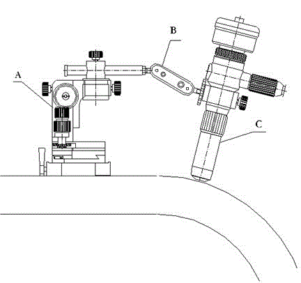
[0027] like figure 2 As shown, a split-type on-site metallographic microscope of the present invention adopts a split-type structure, including an independent microscope base A and a mirror body C with optical system components, and the microscope base A and mirror body C are detachable A steering adjustment bracket B is connected, and one end of the steering adjustment bracket B is fixed on the microscope base A of the matching on-site metallurgical microscope, and the other end is fastened to the mirror body C with an optical system. On the premise of ensuring the stability of the mirror body C, according to the detection needs, the steering adjustment bracket B is adjusted in multiple directions so that the tested surface is perpendicular to the optical system in the mirror body C, so as to obtain a relatively clear picture.

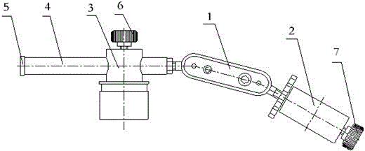
[0028] like image 3 , 4 As shown, the specific structure of the present invention includes a steering adjustment bracket B. The steering adjustme...


PUM


Abstract

A split type field metallographic microscope includes an independent microscope base and a microscope body with an optical system component, a steering adjusting support is detachably connected between the microscope base and the microscope body and includes two long-strip-shaped clamping plates through which clamping adjusting bolts penetrate, and rotatable left ball body and right ball body are clamped at left and right ends between the clamping plates; the left side of the left ball body is connected with an adjusting rod, a base fixing member is arranged on the adjusting rod in a penetrating manner, and the base fixing member is connected with the microscope base; the right side of the right ball body is connected with a microscope body fastening sleeve which is connected with the microscope body, and the bottom part of the microscope base is provided with a magnetic base. The beneficial effects are that the split type field metallographic microscope adopts a split type structure, thereby facilitating adjustment of positions and angles of the microscope body, rapidly and effectively allowing the optical system of the microscope body to be vertical to a to-be-detected surface, ensuring the metallographic structure of a whole field of view to be clear, and obtaining high imaging quality.

Description

technical field [0001] The invention relates to a split type on-site metallographic microscope. Background technique [0002] On-site metallographic microscope is an optical instrument with small precision optical structure for microstructure analysis of important parts that cannot be cut and sampled. When in use, after finishing the steps of grinding, polishing and eroding the workpiece, it is directly adsorbed on the workpiece for tissue observation. [0003] In the existing on-site metallographic microscope, the microscope base and the mirror body of the microscope are integrated. Due to the special working conditions on site, when observing the on-site metallographic grinding surface, the selection of the observation position is mainly determined by the operator. [0004] After the microscope is placed, it is difficult to be perpendicular to the optical system in the mirror body. In order to obtain relatively clear pictures, the operator often needs to spend a lot of ti...

Claims


Application Information

Patent Timeline
Patent Type & Authority Applications(China)
IPC IPC(8): G02B21/24G02B21/00G01N21/84
Inventor 胡新芳张鸿武马永泉刘蕊刘爽邵明星赵永宁荆象阳傅敏
Owner STATE GRID CORP OF CHINA
Why Eureka
Try Eureka