
Mold for manufacturing bulb lamps and rapid demolding method

A technology for bulb lamps and molds, which is applied in the field of mold manufacturing, can solve problems affecting work efficiency and waste of manpower, and achieve the effect of ensuring aesthetics

Active Publication Date: 2020-08-14
中山市智典照明有限公司
View PDF11 Cites 1 Cited by
  • Summary
  • Abstract
  • Description
  • Claims
  • Application Information

AI Technical Summary

Problems solved by technology

[0003] In the prior art mold, after injection molding, the shape of the formed bulb remains in the molding groove of the mold, and it needs to be manually taken out from the molding groove when it is taken out, which affects its work efficiency and causes a certain amount of manpower waste

Method used


Image

  • Mold for manufacturing bulb lamps and rapid demolding method
  • Mold for manufacturing bulb lamps and rapid demolding method
  • Mold for manufacturing bulb lamps and rapid demolding method

Examples


Embodiment 1

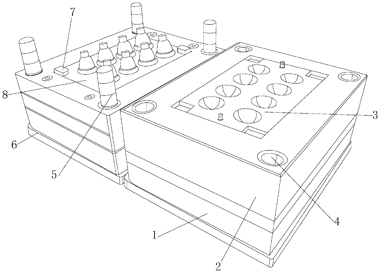
[0029] see figure 1 , a mold for manufacturing bulb lamps of the present invention and a quick demoulding method, including a base plate 1, a lower mold base 2, a forming base structure 3, a positioning hole 4, a positioning column 5, a top seat 6, a rectangular limit block 7 and The upper mold base 8 and the top of the bottom sheet 1 are integrally formed with a lower mold base 2, and the four ends of the lower mold base 2 are provided with positioning holes 4, and the inside of the positioning hole 4 is plugged with a positioning column 5, and the positioning column 5 is fixed on the top of the top base 6. end, the upper mold base 8 is embedded in the inner side of the top base 6, and the four ends of the top of the upper mold base 8 are fixed with rectangular limit blocks 7, and the inner top side of the lower mold base 2 is embedded with a forming base structure 3, through which the forming base structure 3 The product is ejected directly after molding.

[0030] see fig...

Embodiment 2

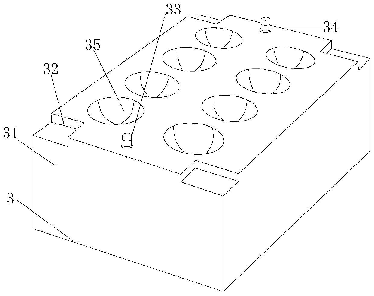
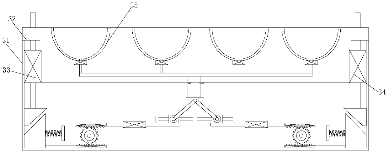
[0036] A mold for manufacturing a bulb lamp and a quick demoulding method of the present invention, the position of the limiting groove 32 corresponds to the position of the rectangular limiting block 7, and the length and width of the limiting groove 32 are greater than the length of the rectangular limiting block 7 And width 0.5cm, is conducive to limit, the structure of left strut assembly 33 and right strut assembly 34, size are all the same, and left and right strut assembly 33 and right strut assembly 34 are symmetrical left and right inside frame body 31, top A total of eight ejector rods 3374 are provided, and the eight ejector rods 3374 are respectively inserted into the inside of the forming groove 35, and the ejector rods 3374 and the forming groove 35 are seamlessly matched to ensure the aesthetics of product molding.

[0037] The present invention provides a mold for manufacturing bulb lamps and a rapid demoulding method through improvement, and its working princip...


PUM


Abstract

The invention discloses a mold for manufacturing bulb lamps and a rapid demolding method. The mold includes a bottom sheet, a lower mold seat, a forming base structure, positioning holes, positioningcolumns, a top seat, a rectangular limiting block and an upper mold seat, the lower mold seat is integrally formed at the top of the bottom sheet, the positioning holes are formed in the four ends ofthe lower mold seat, and the positioning columns are matched with the inner sides of the positioning holes in inserted and connected modes. The forming base structure is arranged on the inner side ofthe lower mold seat in an optimizing mode, after a product is formed, the upper mold seat is out of contact with a pressing rod, a lower pressure block is reset under the elastic force of a spring, sothat a lower rod body drives an upper rod body to move to the right through a gear, and the upper rod body enables a supporting frame to drive an ejector rod to rise in a forming groove through a bearing block, and the product is ejected out from the inner part of the forming groove to perform demolding.

Description

technical field [0001] The invention relates to the related field of mold manufacturing, in particular to a mold for manufacturing a bulb lamp and a rapid demoulding method. Background technique [0002] The largest market for LED bulb lighting is the civilian market, and the most used by citizens is spherical bulbs, so LED bulbs are a new type of green light source that replaces traditional incandescent bulbs. The bulb shape of LED bulbs adopts a spherical design , The bulb shape of the bulb lamp is usually manufactured by using a mould. [0003] After the injection molding of the mold in the prior art, the shape of the shaped bulb remains in the molding groove of the mould, and it needs to be manually taken out from the molding groove when it is taken out, which affects its work efficiency and causes a certain amount of manpower waste. Contents of the invention [0004] Therefore, in order to solve the above disadvantages, the present invention provides a mold for manuf...

Claims


Application Information

Patent Timeline
Patent Type & Authority Applications(China)
IPC IPC(8): B29C45/26B29C45/40
CPCB29C45/26B29C45/4005B29C2045/2683B29L2031/7472
Inventor 邓旭东
Owner 中山市智典照明有限公司
Learn More