
Double poloidal field coils

A poloidal field, field coil technology, used in superconducting magnets/coils, magnetic objects, greenhouse gas reduction, etc.

Pending Publication Date: 2020-08-21
TOKAMAK ENERGY
View PDF25 Cites 2 Cited by
  • Summary
  • Abstract
  • Description
  • Claims
  • Application Information

AI Technical Summary

Problems solved by technology

However, a small-diameter center post is required, which presents challenges in the design of the ring magnets required for plasma stability

Method used


Image

  • Double poloidal field coils
  • Double poloidal field coils
  • Double poloidal field coils

Examples


Embodiment Construction

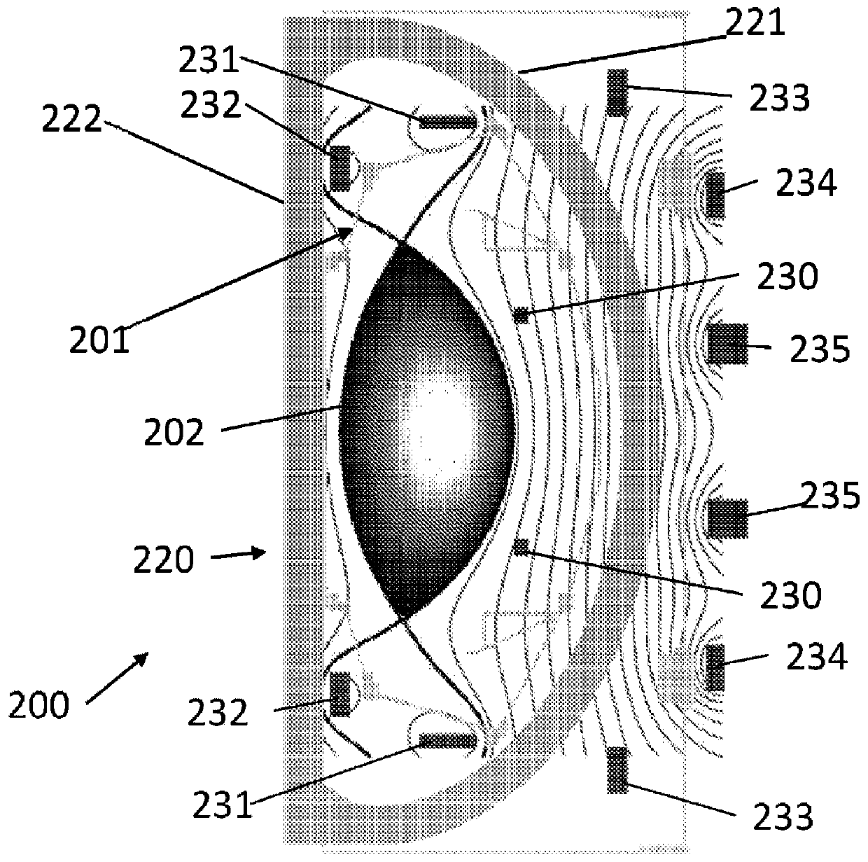
[0022] exist figure 2 A cross-section of one side of the tokamak is shown in . The tokamak 200 comprises: a toroidal plasma chamber 201 ; a toroidal field (TF) coil 220 having a return arm 221 and a center post 222 ; and poloidal field (PF) coils 230 , 231 , 232 , 233 , 234 , 235 . The TF coil 220 provides a toroidal magnetic field in the plasma chamber 201 . The PF coils perform various functions such as merge compression (MC) coil 230 to provide pulses to induce plasma, and shunt coils 231, 232 to elongate the plasma envelope 202 during operation of the tokamak. Broadly speaking, PF coils can be divided into two groups - the first group (which includes the MC coil 230) is energized only for short periods of time, typically during the initiation of the plasma; the second group (which includes the shunt coil 231 ) is energized for a long period of time during the operation of the tokamak.

[0023] Each PF coil is typically constructed as a single conductor loop. The condu...


PUM

PropertyMeasurementUnit
thicknessaaaaaaaaaa

Abstract

The invention discloses a poloidal field coil assembly for use in a tokamak. The poloidal field coil assembly comprises inner and outer poloidal field coils and a controller. The inner poloidal fieldcoil is configured for installation inside a toroidal field coil of the tokamak. The outer poloidal field coil is configured for installation outside the toroidal field coil. The controller is configured to cause current to be supplied to the inner and outer poloidal field coils such that the combined magnetic field produced by the inner and outer poloidal field coils has a null at the toroidal field coil.

Description

technical field [0001] The present invention relates to tokamak plasma chambers. In particular, the invention relates to the positioning of poloidal field coils relative to toroidal field coils. Background technique [0002] The challenges of generating fusion power are complex. In addition to the tokamak, many alternatives have been proposed, but none have produced comparable results to the best currently operating tokamaks, such as JET. [0003] World fusion research has entered a new phase after the start of construction of ITER (International Thermonuclear Experimental Reactor), the largest and most expensive (about 15 billion euros) tokamak device ever built. A successful path to commercial fusion reactors requires long pulses, stable operation, and the high efficiencies needed to make electricity generation economical. These three conditions are difficult to achieve simultaneously, and the planned procedure will require years of experimental research as well as theo...

Claims


Application Information

Patent Timeline
Patent Type & Authority Applications(China)
IPC IPC(8): G21B1/05H01F6/06H01L39/14H01B12/00H10N60/20
CPCG21B1/057H01F6/06Y02E30/10
Inventor 彼得·巴克斯顿
Owner TOKAMAK ENERGY
Learn More