Piston circumferential surface machining fixing device utilizing connecting rod motion principle

A technology of connecting rod movement and fixing device, applied in the field of pistons, can solve the problems of narrowing of the moving range of the tool, affecting the adjustment of the tool, troublesome clamping of the fixture, etc., to achieve the effect of increasing the scope of use, reducing the cost of equipment, and avoiding the trouble of replacing the fixture

Inactive Publication Date: 2020-08-25
朱洁怡
View PDF8 Cites 1 Cited by
  • Summary
  • Abstract
  • Description
  • Claims
  • Application Information

AI Technical Summary

Problems solved by technology

[0003] It is usually necessary to fix the piston through a fixture when cutting the annular groove on the circumferential surface of the piston. However, the existing fixture is troublesome to clamp. It is often impossible to clamp stably by lathe directly. Therefore, it is usually necessary to formulate different types of pistons. Different special fixtures lead to a wide variety of fixtures, waste of material costs, and bring certain troubles to the processing of different types of pistons, reducing work efficiency, and some of the existing fixtures are clamped and fixed by the circumferential surface of the piston, resulting in tool movement The scope is reduced, which affects the adjustment of the tool and makes processing difficult

Method used


Image

  • Piston circumferential surface machining fixing device utilizing connecting rod motion principle
  • Piston circumferential surface machining fixing device utilizing connecting rod motion principle
  • Piston circumferential surface machining fixing device utilizing connecting rod motion principle

Examples


Embodiment Construction

[0025] The following will clearly and completely describe the technical solutions in the embodiments of the present invention with reference to the accompanying drawings in the embodiments of the present invention. Obviously, the described embodiments are only some, not all, embodiments of the present invention. Based on the embodiments of the present invention, all other embodiments obtained by persons of ordinary skill in the art without making creative efforts belong to the protection scope of the present invention.

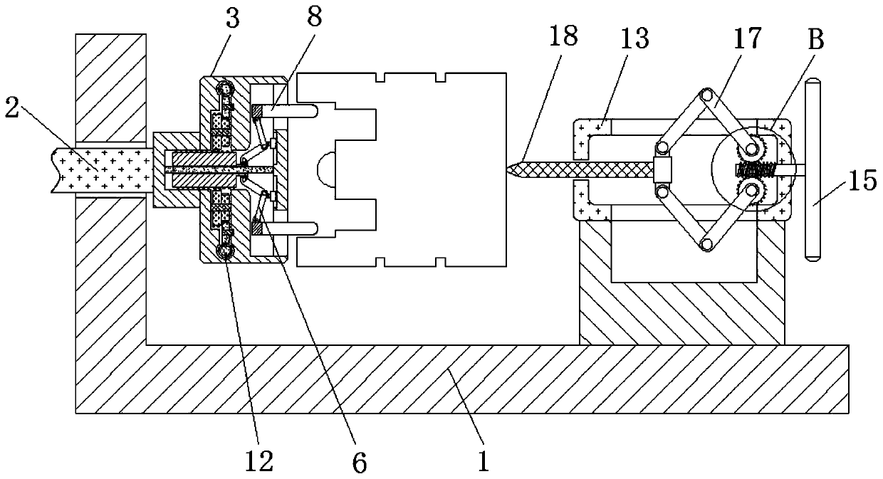
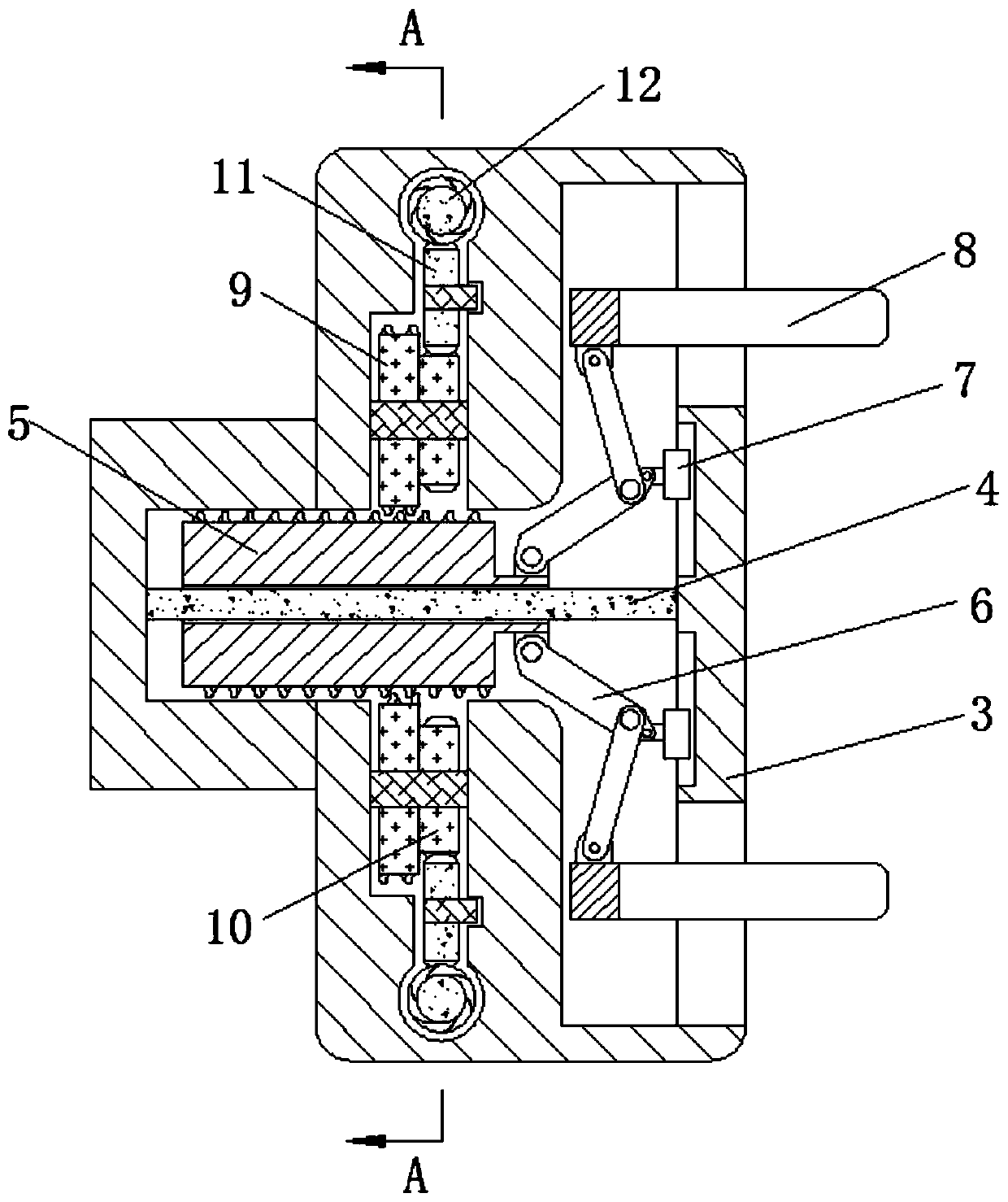
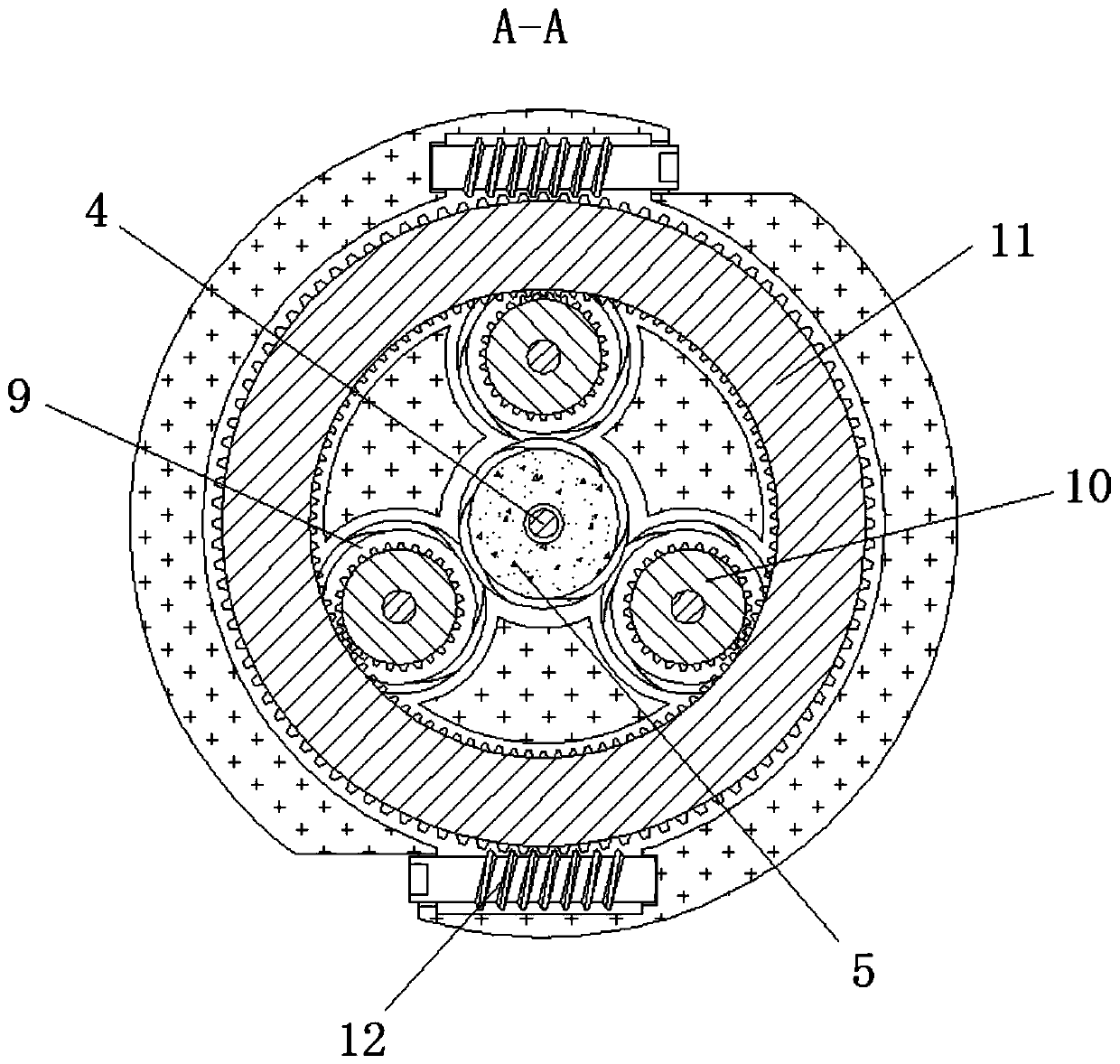
[0026] see Figure 1-4 , a piston circumferential surface processing and fixing device using the principle of connecting rod movement, including a base 1, a main shaft 2, a fixture 3, a guide rod 4, a threaded rod 5, a clamping rod 6, a limit slider 7, a clamping claw 8, a screw thread Block 9, connecting gear 10, ring gear 11, adjusting rod 12, fixed block 13, fixed screw rod 14, runner 15, fixed gear 16, fixed rod 17, push rod 18.

[0027] The positions and...


PUM


Abstract

The invention relates to the technical field of pistons, and discloses a piston circumferential surface machining fixing device utilizing the connecting rod motion principle. The piston circumferential surface machining fixing device utilizing the connecting rod motion principle comprises a base, a main shaft is movably connected in the inner part of the base, a clamp is fixedly connected on the outer portion of the main shaft, a guide rod is fixedly connected in the inner part of the clamp, a threaded rod is slidably connected on the outer portion of the guide rod, a clamping rod is hinged tothe outer portion of the threaded rod, a limiting sliding block is hinged to the outer portion of the clamping rod, a clamping jaw is hinged to the outer portion of the clamping rod, and a threaded block is in threaded connection with the outer portion of the threaded rod. According to the piston circumferential surface machining fixing device utilizing the connecting rod motion principle, the effect of clamping a piston is achieved through cooperative use of the guide rod, the threaded rod, the clamping rod, the limiting sliding block and the clamping jaw, due to the fact that the clamping jaw is movably connected with the clamp, pistons of different models and sizes can be clamped, the application range of the device is enlarged, preparation of special clamping pieces is reduced, the trouble of replacing the clamp is avoided, the device cost is further reduced, and the piston machining efficiency is improved.

Description

technical field [0001] The invention relates to the technical field of pistons, in particular to a processing and fixing device for the circumferential surface of a piston using the principle of connecting rod movement. Background technique [0002] The piston is a reciprocating part in the cylinder block of an automobile engine. The basic structure of the piston can be divided into top, head and skirt. The top of the piston is the main part of the combustion chamber, and its shape is related to the selected combustion chamber. Gasoline engines mostly use flat-top pistons, which have the advantage of small heat absorption area. There are often various pits on the top of diesel engine pistons, and their specific shapes, positions and sizes must be compatible with the requirements of diesel engine mixture formation and combustion. Moreover, the circumferential surface of the piston is often provided with an annular groove. [0003] It is usually necessary to fix the piston th...

Claims


Application Information

Patent Timeline
Patent Type & Authority Applications(China)
IPC IPC(8): B23Q3/12
CPCB23Q3/12B23Q2703/10
Inventor 朱洁怡
Owner 朱洁怡
Why Eureka
Try Eureka