
Split type upper elastic sheet structure, driving device and electronic equipment

A split-type, shrapnel technology, applied in the direction of electromechanical devices, electrical components, electric components, etc., can solve the problems of occupying the space of the motor and failing to effectively use the internal space of the motor, so as to increase reliability and stability and ensure the assembly process Sexuality, the effect of increasing the available space

Pending Publication Date: 2020-08-25
NEW SHICOH MOTOR CO LTD
View PDF0 Cites 0 Cited by
  • Summary
  • Abstract
  • Description
  • Claims
  • Application Information

AI Technical Summary

Problems solved by technology

The disadvantage of the above structure is that the outer frame occupies a small space inside the motor, and the internal space of the motor cannot be effectively utilized.

Method used


Image

  • Split type upper elastic sheet structure, driving device and electronic equipment
  • Split type upper elastic sheet structure, driving device and electronic equipment
  • Split type upper elastic sheet structure, driving device and electronic equipment

Examples


Embodiment 1

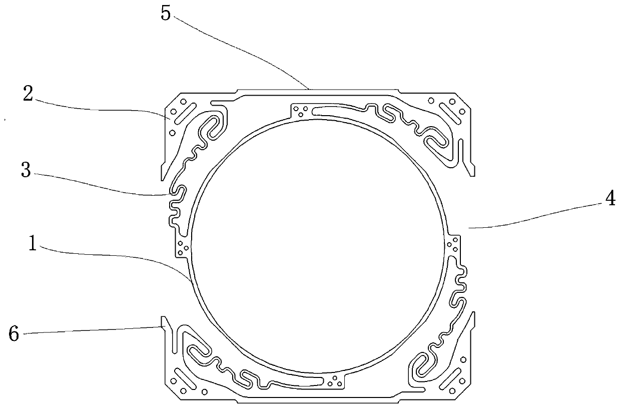
[0024] see figure 2 , in this embodiment, the fixing part (2) includes a first fixing part (21), a second fixing part (22), a third fixing part (23) and a first fixing part (23) arranged along the outside of the inner ring part (1). Four fixed parts (24);

[0025] The first fixing part (21) and the second fixing part (22) are connected through an outer frame (5), and the third fixing part (23) and the fourth fixing part (24) are connected through another outer frame (5) ; The first fixing part (21) and the fourth fixing part (24) are provided with a gap (4), and the second fixing part (22) and the third fixing part (23) are provided with another gap (4).

[0026] By adopting the above structure, this embodiment increases the available space inside the motor and increases the reliability and stability of the motor.

Embodiment 2

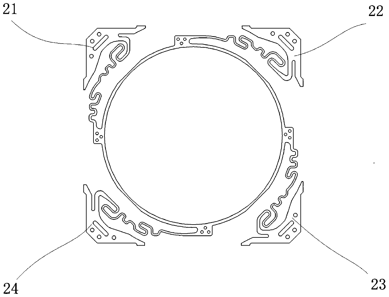
[0028] see image 3 , in this embodiment, the fixing part (2) includes a first fixing part (21), a second fixing part (22), a third fixing part (23) and a first fixing part (23) arranged along the outside of the inner ring part (1). Four fixed parts (24);

[0029] A gap (4) is provided between any adjacent fixed parts (2), and is separated into a split structure by the gap (4).

[0030] By adopting the above structure, this embodiment increases the available space inside the motor and increases the reliability and stability of the motor.

[0031] From Embodiment 1 and Embodiment 2, it can be seen that the key point of the design of this application is that there is a gap (4) between the fixing parts (2), and the gap (4) is used to separate it into an independently arranged split structure. The setting of the gap (4) is not limited to the left and right sides, the upper and lower sides, and the upper, lower, left, and right sides are separated. By ensuring the assembling manu...

Embodiment 3

[0033] A voice coil motor has a split-type upper elastic piece structure as described in Embodiment 1 or Embodiment 2. In this embodiment, other structures of the voice coil motor are the same as those of the prior art, so details are not described here.


PUM


Abstract

The invention discloses a split type upper elastic piece structure which comprises an inner ring part, a plurality of fixing parts arranged along the outer side of the inner ring part, and elastic armparts used for connecting the inner ring part with the fixing parts. The inner ring part comprises an annular main body; the outer side of the inner ring part is connected with the first ends of theelastic arm parts, and the second ends of the elastic arm parts are connected with the fixing parts; and the fixing parts are distributed in the outer circumferential direction of the inner ring part;gaps are formed between the fixing parts; and the fixing parts are separated into a split structure through the gaps. According to the invention, due to the fixing parts, an outer frame for connection is cancelled; and the fixing parts are separated into an independent split structure through the gaps, thereby enlarging the available space in the motor, and improving the reliability and stabilityof the motor.

Description

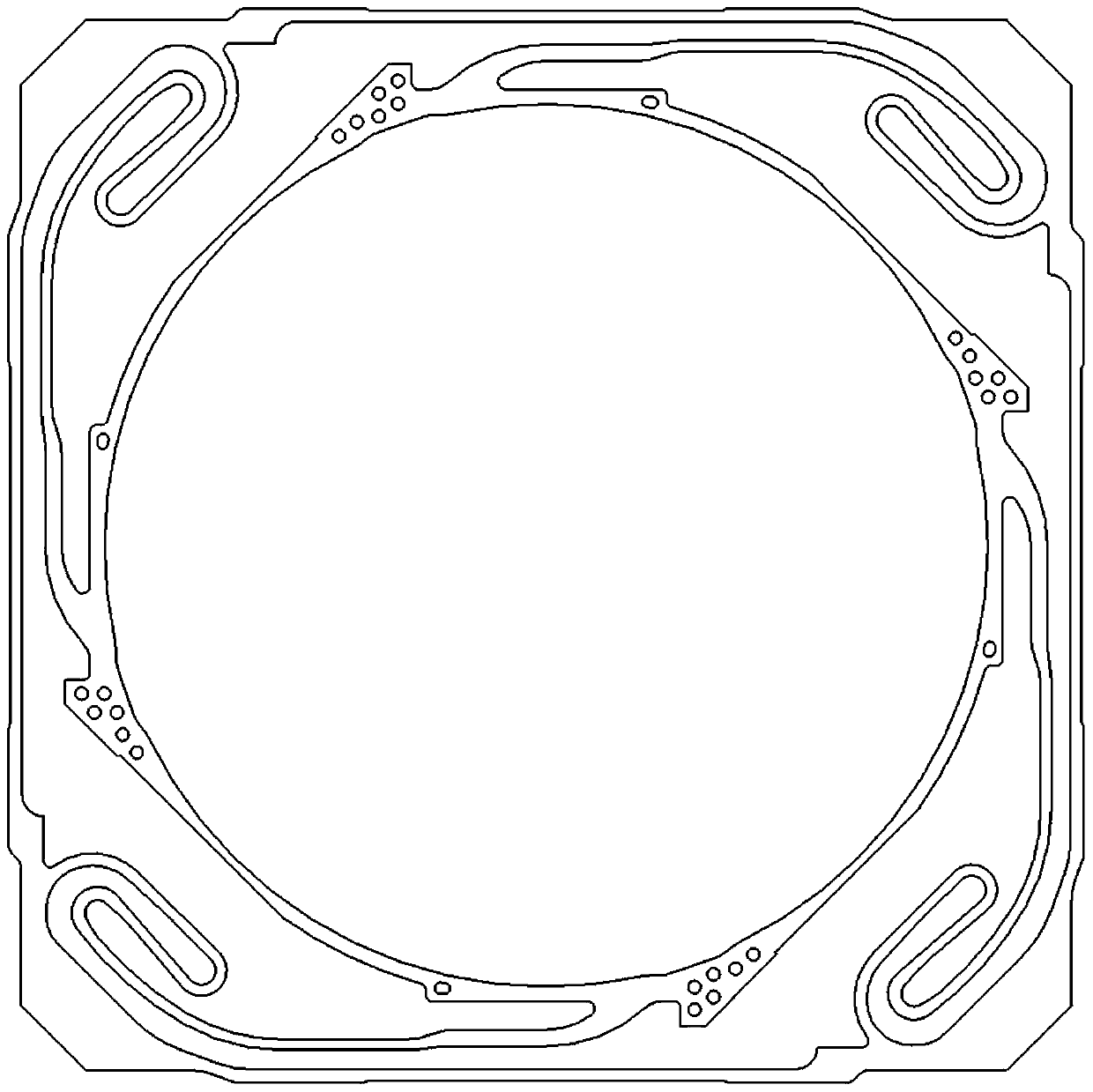
technical field [0001] The present invention relates to the field of voice coil motors, in particular to a split-type upper shrapnel structure, a driving device and electronic equipment. Background technique [0002] A voice coil motor is a device that converts electrical energy into mechanical energy, and realizes linear and limited swing angle motion. A device that uses the interaction between the magnetic field from the permanent magnet steel and the magnetic poles in the magnetic field generated by the energized coil conductor to produce regular motion. [0003] see figure 1 , the fixing part of the upper elastic sheet structure of the existing voice coil motor is integrally connected through the outer frame, and is positioned in the XY direction by a plurality of protruding features. The disadvantage of the above structure is that the outer frame occupies a small space inside the motor, and the internal space of the motor cannot be effectively utilized. Contents of ...

Claims


Application Information

Patent Timeline
Patent Type & Authority Applications(China)
IPC IPC(8): H02K33/00H02K41/02
CPCH02K33/00H02K41/02
Inventor 冯东辉王林
Owner NEW SHICOH MOTOR CO LTD
Learn More