rotary piston pump

A rotary piston pump and rotary piston technology, applied in the direction of rotary piston pumps, rotary piston machines, rotary piston/swing piston pump components, etc., can solve problems such as wear, loss, and leaky transportation, and achieve Effects of optimized layout, slow moving out movement, and reduced flow resistance

Active Publication Date: 2022-06-24
BMA BRAUNSCHWEIGISCHE MASCHINBAUANSTALT AG
View PDF8 Cites 0 Cited by
  • Summary
  • Abstract
  • Description
  • Claims
  • Application Information

AI Technical Summary

Problems solved by technology

[0005] Disadvantages of such rotary piston pumps are the relatively small pump volume per revolution and the high wear at the rotary piston and sealing elements if the sealing elements are not forcibly guided
Here, the piston contour causes the sealing element to be pressed away from the piston and thus leads to leaks and conveying losses
In order to prevent this, increased pressing forces must be applied, which lead to increased energy requirements and increased wear

Method used


Image

  • rotary piston pump
  • rotary piston pump
  • rotary piston pump

Examples


Embodiment Construction

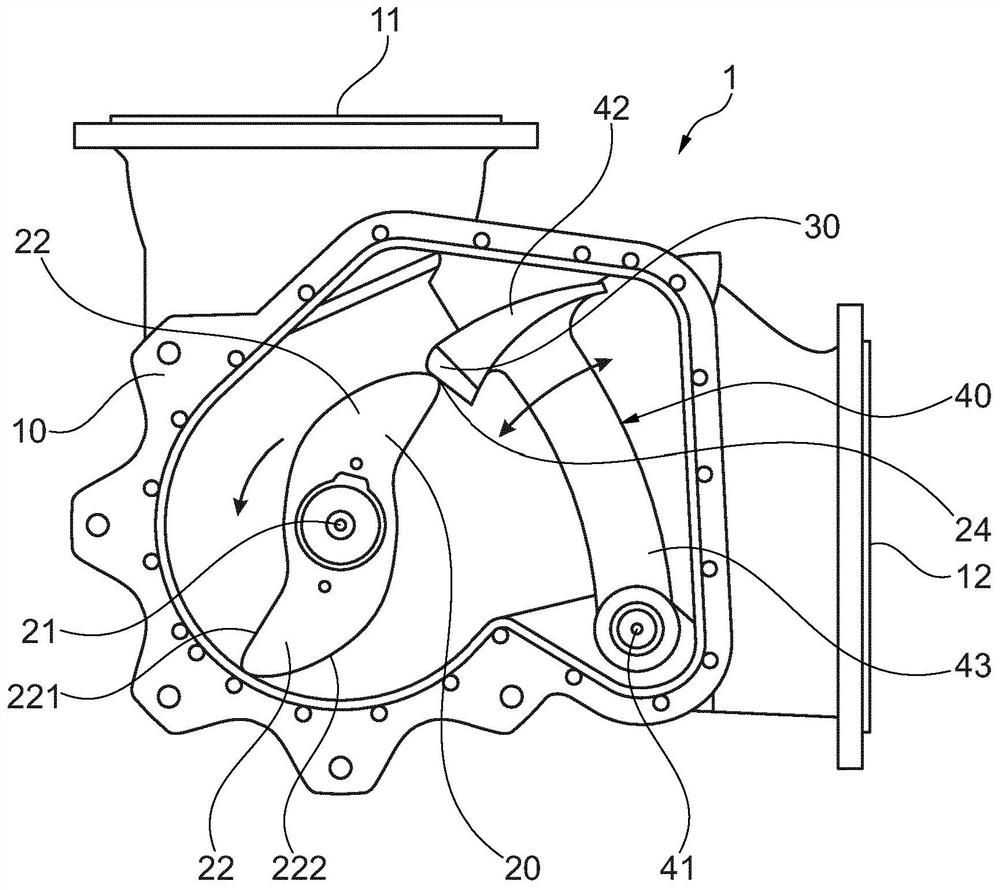
[0030] figure 1 A rotary piston pump 1 is shown in a schematic cross-section with a housing 10 with an inlet 11 on the upper side and an inlet 11 oriented substantially perpendicular to the inlet 11 . figure 1 The outlet 12 is arranged on the right. Inside the housing 10 , the rotary piston 20 is rotatably mounted about a rotational axis 21 . A particularly viscous medium, especially slurries in the production of sugar, is conveyed from the inlet 11 to the outlet 12 by means of a rotary piston 20 which has two transport wings 22 on opposite sides. Here, the rotational direction of the rotary piston 20 is counterclockwise, as indicated by the arrow. The rotary piston 20 with the two transport wings 22 partially rolls on the cylindrical housing wall and forms a separation between the inlet side and the outlet side together with the sealing element 30 and the sealing body 42 of the shut-off wing 40 . During the rotation of the rotary piston 20 it runs on the outer contour of s...


PUM


Abstract

The invention relates to a rotary piston pump having: a) a housing (10) with an inlet (11) and an outlet (12) for the medium to be pumped; b) at least one rotary piston (20), It is mounted drivably and rotatably in a housing (10) and has at least two contoured transport wings (22) which transport the medium to be transported from the inlet (11) to the outlet (12); c) and the sealing element (30) of each rotary piston (20), which bears on the sealing body (42) and runs on the contour of the rotary piston (20) during the rotation of the rotary piston (20) And carry out on the different side of transport wing (22) carry out moving from the smallest diameter of rotary piston (20) to the maximum diameter of rotary piston (20) and from the maximum diameter of rotary piston (20) to rotary piston (20) The smallest diameter movement in, wherein, d) the path that the sealing element (30) carries out on the movement side (221) of the transport wing (22) during the movement in is smaller than the path carried out on the side (222) during the movement out .

Description

technical field [0001] The invention relates to a rotary piston pump having: a housing with an inlet and an outlet for the medium to be pumped; at least one rotary piston in a drivable and rotatable manner supported in the housing, and the at least one rotary piston has at least two profiled transport wings that transport the medium to be transported from the inlet to the outlet; and each rotary piston sealing element, which is fastened to the sealing body, in particular pivotably mounted, runs on the contour of the at least one rotary piston during the rotation of the at least one rotary piston and implements a minimum distance from the at least one rotary piston. A movement out of the diameter to the largest diameter of the at least one rotary piston and an in movement from the largest diameter of the at least one rotary piston to the smallest diameter of the at least one rotary piston. Such rotary piston pumps are particularly suitable and provided for pumping highly visco...

Claims


Application Information

Patent Timeline
Patent Type & Authority Patents(China)
IPC IPC(8): F01C21/08F04C2/332F04C2/46F04C15/00
CPCF01C21/08F01C21/0809F04C2/332F04C2/46F04C15/0007F04C2240/20F04C2250/20
Inventor H-H·韦斯滕达普F·阿尔杰斯
Owner BMA BRAUNSCHWEIGISCHE MASCHINBAUANSTALT AG
Why Eureka
Try Eureka