
Gradient combustion self-denitration system of calciner with external combustion chamber

A calcining furnace and combustion chamber technology, applied in the field of flue gas denitrification in the cement industry, can solve the problems of poor reaction effect in the oxygen-lean combustion zone and other problems

Active Publication Date: 2021-11-02
TIANJIN CEMENT IND DESIGN & RES INST
View PDF1 Cites 0 Cited by
  • Summary
  • Abstract
  • Description
  • Claims
  • Application Information

AI Technical Summary

Problems solved by technology

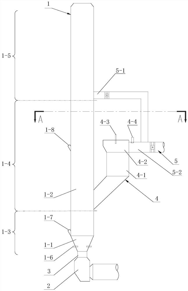
[0005] Aiming at the problems existing in the prior art, the present invention provides a calciner gradient combustion self-denitration system with an external ignition chamber that solves the problem of poor reaction effect in the oxygen-poor combustion zone in the gradient combustion self-denitration system for cement production

Method used


Image

  • Gradient combustion self-denitration system of calciner with external combustion chamber
  • Gradient combustion self-denitration system of calciner with external combustion chamber
  • Gradient combustion self-denitration system of calciner with external combustion chamber

Examples


Embodiment 1

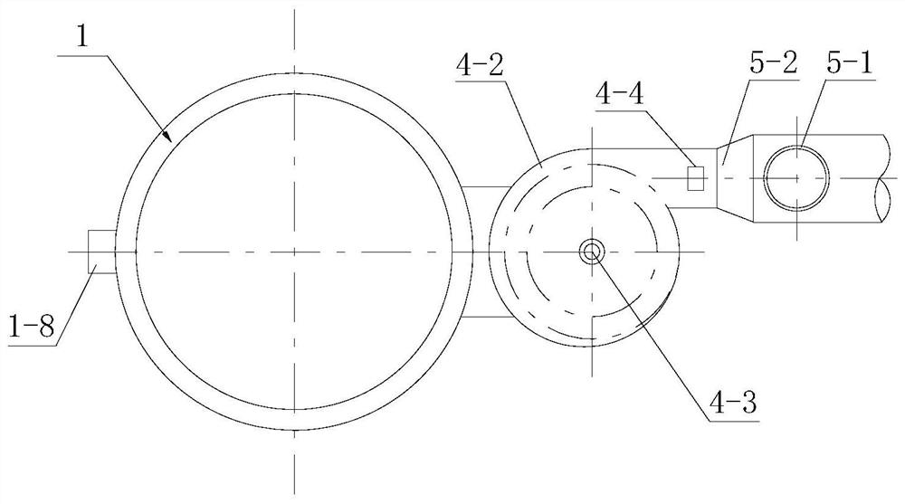
[0019] see figure 1 with figure 2 , a calciner gradient combustion self-denitration system with an external combustion chamber, including a calciner 1. The lower part of the calciner 1 is a conical part 1-1, and the upper part of the calciner 1 is a cylindrical part 1-2. The lower end of the conical portion 1-1 of the calciner 1 communicates with the flue gas outlet of the flue chamber 2 of the rotary kiln of the cement production system. The flue gas from the rotary kiln enters the calciner 1 from the lower end of the calciner 1 . In this embodiment, the lower end of the conical part 1-1 of the calciner 1 is a shrinking columnar part 3 with a reduced diameter for the wind speed at the connection between the flue gas outlet of the smoke extraction chamber 2 and the calciner 1, so as to avoid material subsidence and backflow. .

[0020] The interior of the calciner 1 forms a strong reduction zone 1-3, a weak reduction zone 1-4 and a burnout zone 1-5 sequentially from botto...

Embodiment 2

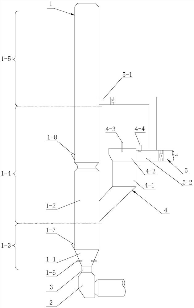
[0039] see image 3 , The technical solution described in this embodiment is different from that in Embodiment 1 in that the cylindrical portion where the weak reduction zone of the decomposition furnace is located is provided with a necking section. This necking section is located below the upper feeding port of the raw meal. The raw meal that enters from the upper feed port of the raw meal has a tendency to move downward under the action of gravity. The design of the necking section makes the section wind velocity at the necking section larger than the wind velocity of the cylindrical section of the calciner, which can effectively reduce the falling height of the raw material and prevent material collapse in the calciner.


PUM


Abstract

The invention discloses a calciner gradient combustion self-denitration system with an external ignition chamber, which belongs to the technical field of cement production and includes a calciner. The interior of the calciner sequentially forms a strong reduction zone, a weak reduction zone and a burnout zone from bottom to top. area, the calciner is provided with a calciner fuel feed port and a calciner raw meal lower feed port connected with the strong reduction area, and the calciner is provided with an upper calciner raw meal feed port connected with the weak reduction area, and the calciner is equipped with There is an upper tertiary air inlet connected to the burnout area, and it is characterized in that it includes an ignition chamber, the ignition chamber has a column cavity, the column cavity is provided with a volute, and the upper part of the column cavity is provided with an ignition chamber fuel feeder. The material port and the volute part are provided with the lower tertiary air inlet, and the volute part introduces the tertiary air entering from the lower tertiary air inlet into the column cavity along the direction tangent to the inner side of the column cavity, and the ignition chamber is close to the lower The tertiary air inlet is provided with the raw material feeding port of the ignition chamber, and the lower part of the column cavity is provided with the outlet of the ignition chamber, and the outlet of the ignition chamber communicates with the weak reduction zone of the calciner.

Description

technical field [0001] The invention belongs to the technical field of flue gas denitrification in the cement industry, and in particular relates to a calciner gradient combustion self-denitration system with an external combustion chamber. Background technique [0002] Nitrogen oxides are gases produced when fossil fuels and air burn at high temperatures and are highly toxic. Nitrogen oxide emissions affect air quality and pose serious hazards to human living environment and health. The cement industry is the third largest emitter of nitrogen oxides after thermal power generation and automobile exhaust. In order to strengthen environmental protection and actively control nitrogen oxide emissions, strict emission standards have been formulated. [0003] In order to further reduce the denitrification operation cost of the enterprise, improve the efficiency of fuel combustion self-denitration, and reduce the secondary pollution in the cement production process, the company h...

Claims


Application Information

Patent Timeline
Patent Type & Authority Patents(China)
IPC IPC(8): F27B19/04F27D17/00B01D53/76B01D53/56
CPCB01D53/56B01D53/76B01D2258/0283F27B19/04F27D17/008
Inventor 陈昌华彭学平胡芝娟李宁林敏燕
Owner TIANJIN CEMENT IND DESIGN & RES INST
Learn More