
Eureka
For R&D, Eureka makes reading and utilizing patents & technical documents easy.
Eureka AIR
Designed for self-driven R&D workflows. Generate viable solutions, solve complex R&D challenges, empower your innovation with AI.

Eureka Materials
Designed for material experts only. Revolutionize your material R&D, from search, analyze, to developing new materials.

TechResearch
Generate reliable direction feasibility study reports for your R&D in just a few steps.

TechSeek
Discover and master advanced knowledge NOW. Basics, ideas, possibilities, all at once.

TechMind
As an expert in R&D Theories, TechMind can generates customized viable solutions instantly.

TechRisk
Analyze your overall solution with one click, know your potential R&D risks in advance.

TechMonitor
Get weekly tech updates, stay abreast of the latest tech innovations and key insights.
Shoveling and throwing machine
An integrated, traveling device technology, applied in the field of shovel throwers, can solve the problems of a large amount of dust, impact force, affecting the service life of equipment, etc., and achieve the effect of prolonging the service life
- Summary
- Abstract
- Description
- Claims
- Application Information
AI Technical Summary
Problems solved by technology
Method used
Image

Examples
Embodiment 1
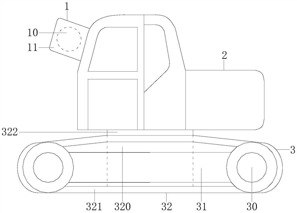
[0024] Example 1 see Figure 1-3 , the present invention provides a technical solution for a shoveling machine: its structure includes a side throwing structure 1, a shoveling machine body 2, and a running device 3, and the shoveling machine body 2 is installed and connected to the side throwing structure 1 and the running device 3, so that The shovel throwing machine body 2 communicates with the side throwing structure 1 and the walking device 3. The side throwing structure 1 is composed of a side feeding frame structure 10 and a side feeding outlet 11. The side feeding outlet 11 is installed on the side feeding frame. In the structure 10, the traveling device 3 includes a traveling wheel 30, a wheel box 31, and an integrated device 32. The wheel box 31 is connected to the traveling wheel 30 and the integrated device 32, and the traveling wheel 30 is bonded to the integrated device 32. The integrated device 32 includes a collection box 320, a conveyor belt 321, and an adapter...
Embodiment 2
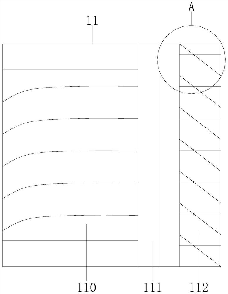
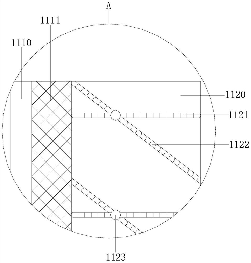
[0026] Example 2 see Figure 4 , 5 , the present invention provides a technical solution for a scraper: the structure of the side feeding frame structure 10 includes an inner rail 100 and a sliding round block 101, the inner rail 100 is connected to the sliding round block 101, and the side feeding frame structure The cushioning performance of 10 reduces the impact force generated by the side throwing port. The inner rail 100 includes a ring slide rail 1000, an inner ring rail 1001, and an inner rail main ring 1002. The ring slide rail 1000 is locked with the inner ring rail 1001. The inner ring rail 1001 is welded to the inner rail main ring 1002, and the collection box 320 includes an inner warehouse ring 3200, an outer warehouse ring 3201, and a knives 3202, and the inner warehouse ring 3200 and the outer warehouse ring 3201 are assembled and connected. The outer warehouse ring 3201 is installed and connected with the knife 3202. When the soil is collected, it moves betwee...
PUM
 Abstract
Description
Claims
Application Information
 - R&D Engineer
- R&D Manager
- IP Professional
- Industry Leading Data Capabilities
- Powerful AI technology
- Patent DNA Extraction
Browse by: Latest US Patents, China's latest patents, Technical Efficacy Thesaurus, Application Domain, Technology Topic, Popular Technical Reports.
© 2024 PatSnap. All rights reserved.Legal|Privacy policy|Modern Slavery Act Transparency Statement|Sitemap|About US| Contact US: help@patsnap.com