
Side-core-pulling injection mold

An injection mold and side core-pulling technology, applied in the field of side-core-pulling injection molds, can solve the problems of inconvenient application, inability to adjust interval time, poor versatility, etc.

Active Publication Date: 2020-10-16
浙大宁波理工学院
View PDF4 Cites 6 Cited by
  • Summary
  • Abstract
  • Description
  • Claims
  • Application Information

AI Technical Summary

Problems solved by technology

However, the above-mentioned side core-pulling injection mold has obvious defects: the side core-pulling distance cannot be adjusted, and the side core-pulling and the mold opening process are completely synchronized, and the interval between the two actions cannot be adjusted, so the actual application is inconvenient, the versatility is poor, and it is difficult to Meet the diverse needs of mold injection molding

Method used


Image

  • Side-core-pulling injection mold
  • Side-core-pulling injection mold
  • Side-core-pulling injection mold

Examples


Embodiment Construction

[0023] The present invention will be further described below in conjunction with the accompanying drawings and specific embodiments.

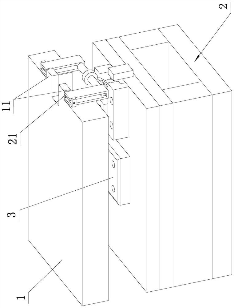
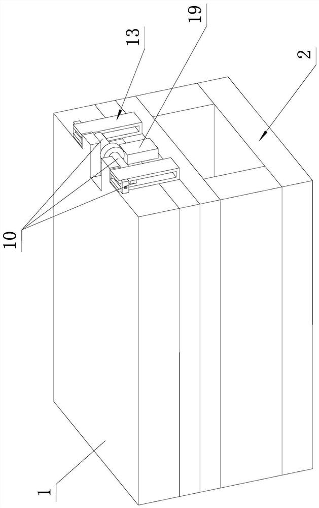
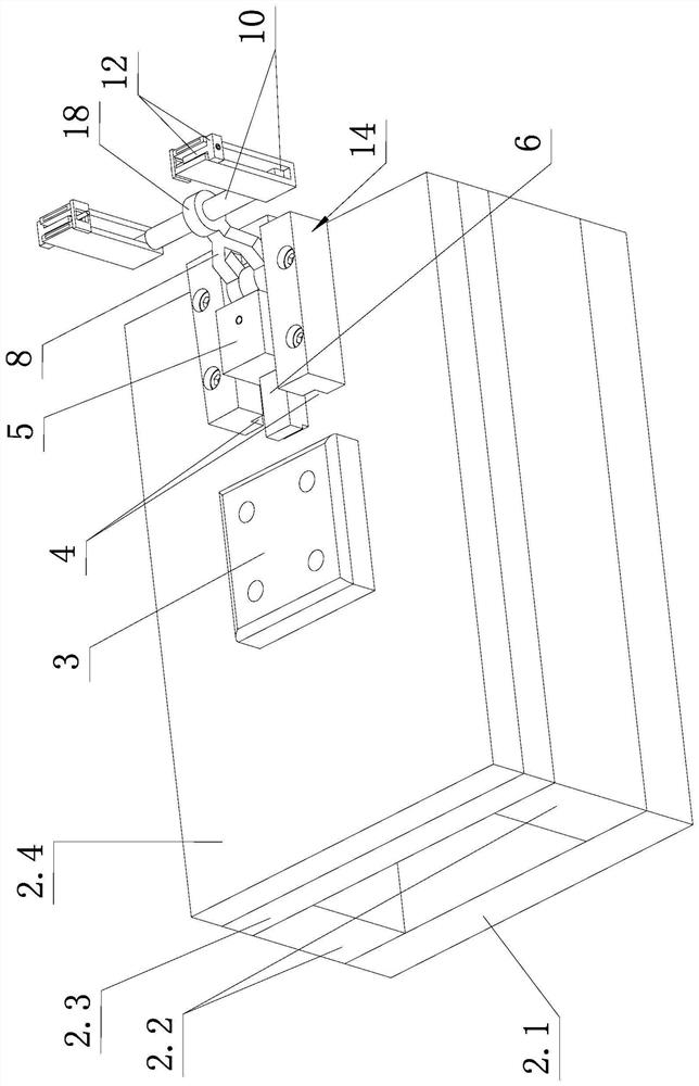
[0024] Such as Figure 1 to Figure 5 As shown, the side core-pulling injection mold of the present invention includes a fixed mold 1 and a movable mold 2, the movable mold 2 is provided with a lower cavity, the lower cavity is fixed with a core 3, and the fixed mold 1 is provided with an upper cavity , after closing the mold, the upper and lower cavities are closed to form a complete cavity. More specifically, the fixed mold is formed by screwing the upper fixed mold seat plate and the lower fixed template, and the upper cavity is located on the lower surface of the fixed template. The movable mold 2 of the present embodiment is formed by screwing the movable mold seat plate 2.1, the spacer 2.2, the backing plate 2.3 and the movable template 2.4 from bottom to top; the core 3 is screwed and fixed on the backing plate 2.3 and the passive templa...


PUM


Abstract

The invention discloses a side-core-pulling injection mold. The side-core-pulling injection mold comprises a fixed mold body and a movable mold body; the movable mold body is provided with a horizontal sliding groove, the interior of the horizontal sliding groove is in sliding fit with a core-pulling sliding block, and an inserting block pointing to the side face of a mold core is arranged on theinner side of the core-pulling sliding block; a hinged shaft is arranged on the outer side of the core-pulling sliding block, the hinged shaft is in clearance fit with a swing rod in a sleeved mode, and a damping ring used for enabling the swing rod to overcome the gravity to keep a swing angle is arranged between the hinged shaft and the swing rod; linkage pins are arranged at the end, away fromthe hinged shaft, of the swing rod; one side of the fixed mold body is connected with vertical rectangular frames through outwards-protruded mounting blocks, and the linkage pins are in sliding fit with the interiors of the vertical rectangular frames; and each vertical rectangular frame is composed of a T-shaped jacking plate and a U-shaped frame, and adjusting screws used for changing the distance between outer transverse plates of the T-shaped jacking plates and the mounting blocks to clamp or loosen the U-shaped frames are arranged between inner vertical plates of the T-shaped jacking plates and the mounting blocks. According to the side-core-pulling injection mold, the side-core-pulling distance can be adjusted, and the time interval between two actions of side-core-pulling and mold opening can be adjusted.

Description

technical field [0001] The invention relates to the field of injection mold equipment, in particular to a side core-pulling injection mold. Background technique [0002] Plastic products have the advantages of high strength, light weight, and low price. They are widely used in various fields of daily life, and in many fields, such as automobile manufacturing, plastic products have largely replaced metal products under the demand for lightweight . At present, in the field of injection molding in my country, a large number of high-end injection molds with complex structures and long lifespans that can be formed at one time still need to be imported in large quantities every year. Therefore, the market prospects for the demand and application of the above-mentioned high-end molds are broad. [0003] Among the above-mentioned high-grade one-time molding molds, there is a type of side core-pulling injection mold that occupies a large share; the characteristic of this type of mol...

Claims


Application Information

Patent Timeline
Patent Type & Authority Applications(China)
IPC IPC(8): B29C45/33B29C45/44
CPCB29C45/33B29C45/44
Inventor 许少锋朱桥辉陈佳伟张学昌高德吴尧锋
Owner 浙大宁波理工学院
Learn More