Gap Elimination Device

A technology of gaps and connecting blocks, which is applied in the field of tread brakes, can solve problems such as loose fit, gaps, and restrictions on the tangential freedom of the brake beam, so as to avoid accidental sliding, realize load transmission, and achieve the effect of good restraint

Inactive Publication Date: 2018-06-05
CRRC QINGDAO SIFANG ROLLING STOCK RES INST
View PDF5 Cites 0 Cited by
  • Summary
  • Abstract
  • Description
  • Claims
  • Application Information

AI Technical Summary

Problems solved by technology

[0004] At present, when the test bench performs the fatigue test on the brake beam, the brake shoe support is directly dropped on the simulated wheel, and the brake shoe support is supported by the top plate arranged at the front and rear of the brake shoe support, thereby limiting the shearing of the brake beam. degrees of freedom
Using this method, although the mechanical structure of the test bench is simplified, the problem is that the connection between the brake shoe and the brake shoe support cannot be truly simulated. At the same time, because the brake shoe support of the brake beam and the brake beam body have 1: The inclination angle of 20, when the brake shoe support is placed on the cylindrical simulated wheel, it will bring the disadvantages of not being tightly fitted and having a gap in the middle

Method used


Image

  • Gap Elimination Device
  • Gap Elimination Device
  • Gap Elimination Device

Examples


Embodiment Construction

[0024] In the following, the present invention will be specifically described through exemplary embodiments. It should be understood, however, that elements, structures and characteristics of one embodiment may be beneficially incorporated in other embodiments without further recitation.

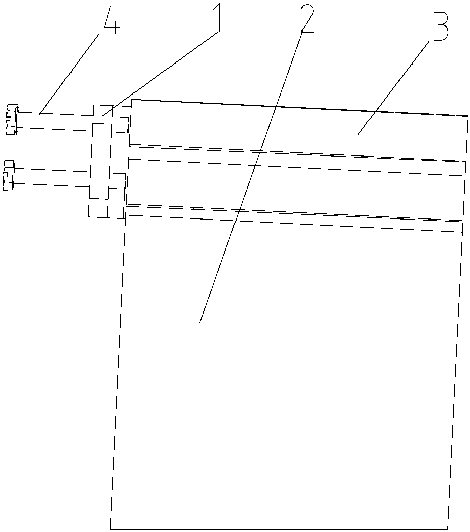
[0025] In the description of the present invention, it should be noted that in the present invention, the directions or positional relationships indicated by "upper", "lower", "top" and "bottom" are based on the attached image 3 The positional relationship shown is only for the convenience of describing the present invention and simplifying the description, but does not indicate or imply that the referred device or element must have a specific orientation, be constructed and operated in a specific orientation, and therefore cannot be construed as limiting the present invention .

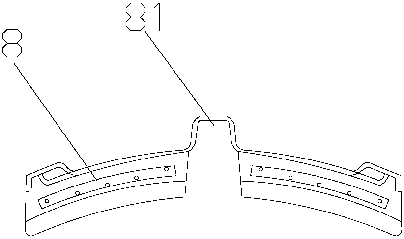
[0026] see image 3 as well as Figure 4 , are respectively the front view and the side view of the gap elim...


PUM


Abstract

A gap elimination device provided by the present invention is used to eliminate a gap between a brake shoe and a brake head at a brake beam fatigue test, and comprises a connecting block capable of connecting the brake shoe and the brake head. The top of the connecting block is a trapezoidal end matching a trapezoidal groove on the brake head, and opening grooves are arranged on the gradient surfaces at the two sides of the trapezoidal end. Adjusting blocks capable of moving in the opening grooves match in the opening grooves, and the positions of the adjusting blocks in the opening grooves are moved to eliminate a gap between the top side surface of the connecting block and the brake head. The gap elimination device is equipped with the connecting block and the adjusting blocks according to the shape of the gap between the brake shoe and the brake head, thereby not only being able to eliminate the gap, but also being able to realize the stepless adjustment.

Description

technical field [0001] The invention relates to the field of tread brakes of rail transit vehicles, in particular to an eliminating device for eliminating the gap between a brake shoe and a brake shoe support. Background technique [0002] The brake beam is the most important part of the basic braking device of the railway freight car. When the vehicle is braking, the braking force is transmitted to the brake shoe through the brake beam, and then the vehicle is braked. The fatigue test of the brake beam is the assessment An important measure of brake beam reliability. In the fatigue test of the brake beam, the installation gaps affecting the test results should be eliminated, so that the load can be applied at a set frequency during the test without increasing the load application distance; at the same time, the brake beam under test The position does not change so as to ensure the accuracy of the test. [0003] The braking of a railway vehicle is through the brake shoe pr...

Claims


Application Information

Patent Timeline
Patent Type & Authority Patents(China)
IPC IPC(8): G01M17/08
CPCG01M17/08
Inventor 金星孙峰于浩然侯丹
Owner CRRC QINGDAO SIFANG ROLLING STOCK RES INST
Why Eureka
Try Eureka