
Method for controlling reactive voltages of transformer substation based on magnetic control reactor (MCR)

A voltage control method and substation technology, applied in reactive power compensation, AC network voltage adjustment, reactive power adjustment/elimination/compensation, etc., can solve problems such as voltage instability, switching oscillation, frequent action, etc. The effect of small wave, low voltage level and high reliability

Active Publication Date: 2011-05-11
GUANGXI POWER GRID CO LTD NANNING POWER SUPPLY BUREAU
View PDF4 Cites 9 Cited by
  • Summary
  • Abstract
  • Description
  • Claims
  • Application Information

AI Technical Summary

Problems solved by technology

[0005] (1) This method is based on the fixed upper and lower limits of voltage reactive power, without considering the mutual coordination relationship between reactive power and voltage;
[0006] (2) The information used for calculation and analysis is random and dispersed, leading to blind uncertainty in control decisions, which is actually manifested as frequent adjustment of devices, which is likely to cause voltage instability;
[0007] (3) The sequence of actions of the two types of equipment has a great influence on the control results. If the sequence is improper, frequent actions, switching oscillations, etc. will occur;
[0008] (4) As long as it enters the qualified area, it will no longer be adjusted, which may cause the system to run on the edge of the voltage or power qualified state for a long time, and fail to control the system in the rated optimal operating state;
[0009] (5) The control of capacitors and on-load tap taps is a step-by-step voltage regulation method, and is strictly limited by the number of switching times per day. It cannot adjust the output reactive power smoothly in real time to ensure line voltage stability and reactive power balance.

Method used


Image

  • Method for controlling reactive voltages of transformer substation based on magnetic control reactor (MCR)
  • Method for controlling reactive voltages of transformer substation based on magnetic control reactor (MCR)
  • Method for controlling reactive voltages of transformer substation based on magnetic control reactor (MCR)

Examples


Embodiment Construction

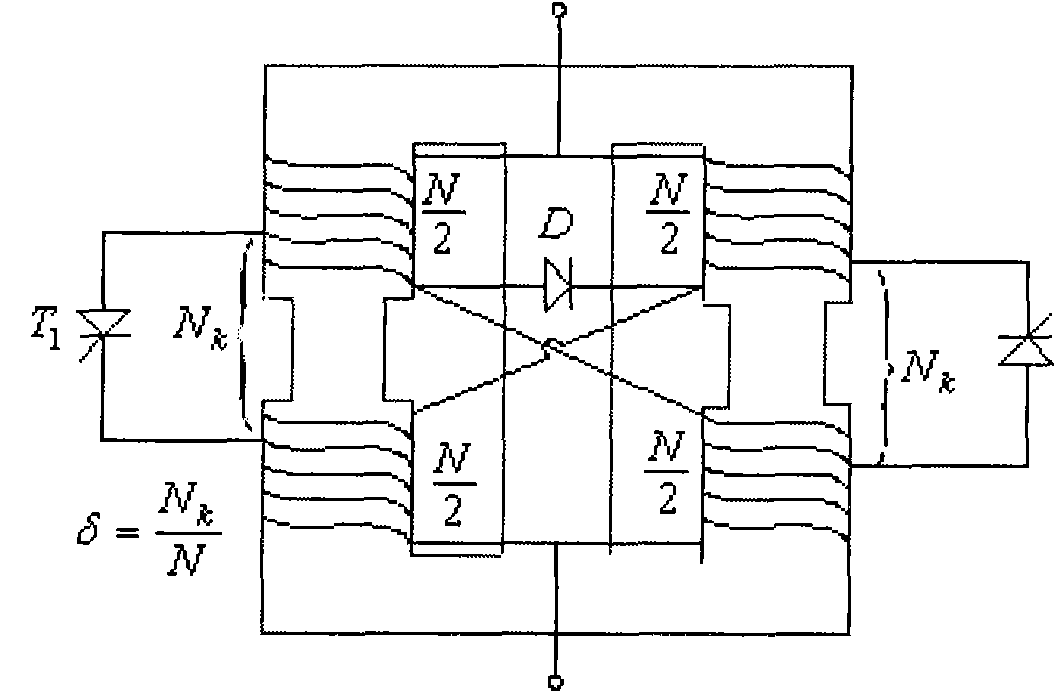
[0038] In the present invention, the MCR body is an iron-core transformer, and the coil wiring principle of the auto-excited MCR is as follows: figure 1 As shown, the number of turns symmetrically wound on the side columns of the reactor is Of the two coils, the windings of each leg have a tap ratio of The taps are connected between them with a thyristor T 1 , T 2 , the upper and lower main windings of different cores are cross-connected and connected in parallel to the power supply, and the power supply voltage is e=E m sin ωt. When the MCR winding is connected to the supply voltage, the thyristor T 1 , T 2 A voltage around 1% of the supply voltage is induced across the terminals. The positive half cycle of the power supply voltage triggers the conduction of the thyristor T 1 , where N 1 =N-N k , to generate a DC control current i′ in the loop k and i″ k ;Trigger conduction thyristor T in the negative half cycle of power supply voltage 2 , forming a DC control c...


PUM


Abstract

The invention discloses a method for controlling reactive voltages of a transformer substation based on a magnetic control reactor (MCR). The method comprises the following three steps of: voltage time-shared control, counter-voltage adjustment control and closed loop control. By using the characteristics of the MCR capable of smoothly outputting reactive power, the MCR is matched with the conventional capacitor bank and a loaded high-voltage tap in the transformer substation, and comprehensive control and real-time control of the reactive voltages of the transformer substation and the stepless adjustment of the reactive power are realized.

Description

technical field [0001] The invention relates to a substation reactive voltage control method, in particular to a substation reactive voltage control method based on MCR (Magnetically Controlled Reactor). Background technique [0002] The voltage of the power system is one of the important indicators to measure the power quality. Common electrical equipment in power systems, such as asynchronous motors and various electric heating equipment, can only achieve the best results when they are operated at rated voltage. If the voltage deviation is too large, it will inevitably affect the life and efficiency of the equipment. In severe cases, even It will jeopardize the stability and economic operation of the grid. [0003] In the operation of the power system, the regulation of voltage and reactive power has a close relationship. Because the operating voltage level of the power system depends on the balance of reactive power, insufficient reactive power will cause the voltage to...

Claims


Application Information

Patent Timeline
Patent Type & Authority Applications(China)
IPC IPC(8): H02J3/18H02J3/12
CPCY02E40/30
Inventor 黄晓胜陈丹黄维斌韦毅彭泽华何志杰禤亮宋运平曾文君史欢
Owner GUANGXI POWER GRID CO LTD NANNING POWER SUPPLY BUREAU
Learn More