Lamp mounting structure

A lamp installation and lamp body technology, which is applied in the direction of lighting devices, lighting auxiliary devices, lighting device components, etc., can solve problems such as changes in lamp installation angles, discontinuous range of lamp adjustment angles, and inability to be accurate to each installation angle, etc. , to achieve the effect of reliable positioning, improved irradiation effect, and stepless adjustment of irradiation angle

Inactive Publication Date: 2014-05-14
OCEANKING DONGGUAN LIGHTING TECH +2
View PDF3 Cites 9 Cited by
  • Summary
  • Abstract
  • Description
  • Claims
  • Application Information

AI Technical Summary

Problems solved by technology

[0002] The traditional lamp installation structure includes a lamp body and a bracket, and the bracket is connected to the lamp body by screws. Such a structure is easy to install and can adjust the irradiation angle of the lamp, but it is easy to cause relative rotation between the lamp body and the bracket, so that the lamp Undesirable changes in the mounting angle of the
[0003] In order to prevent relative rotation between the lamp body and the bracket, some improvements have been made on the traditional lamp installation structure in the prior art, mainly in two forms: one is to add a toothed plate between the bracket and the lamp body Structure, which adjusts the irradiation angle of the lamp and the connection between the locking bracket and the lamp body through the meshing of the internal teeth and the external teeth; the other is to adjust the irradiation angle of the lamp and the connection between the locking bracket and the lamp body by setting positioning holes. Although the two improved methods can prevent the relative rotation of the lamp body and the bracket, the irradiation angle of the lamp cannot be adjusted steplessly, and can only be adjusted at the meshing place between the inner teeth and the outer teeth or in the positioning hole. In this way, the adjustment angle range of the lamp is Discontinuous, not accurate to every installation angle, which affects the illumination effect of lamps and lanterns in some occasions

Method used


Image

  • Lamp mounting structure
  • Lamp mounting structure
  • Lamp mounting structure

Examples


Embodiment Construction

[0020] In order to make the object, technical solution and advantages of the present invention clearer, the present invention will be further described in detail below in conjunction with the accompanying drawings and embodiments. It should be understood that the specific embodiments described here are only used to explain the present invention, not to limit the present invention.

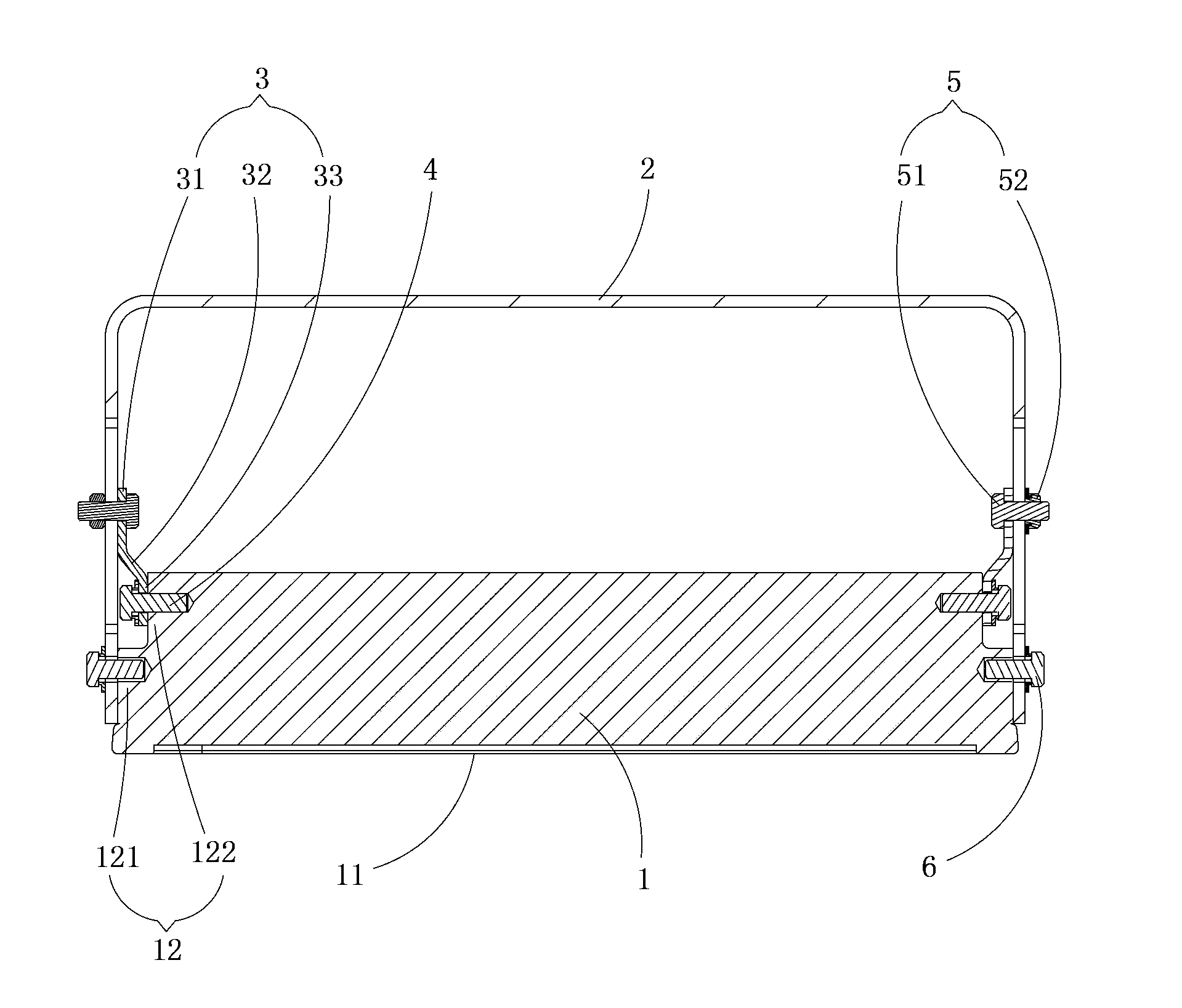
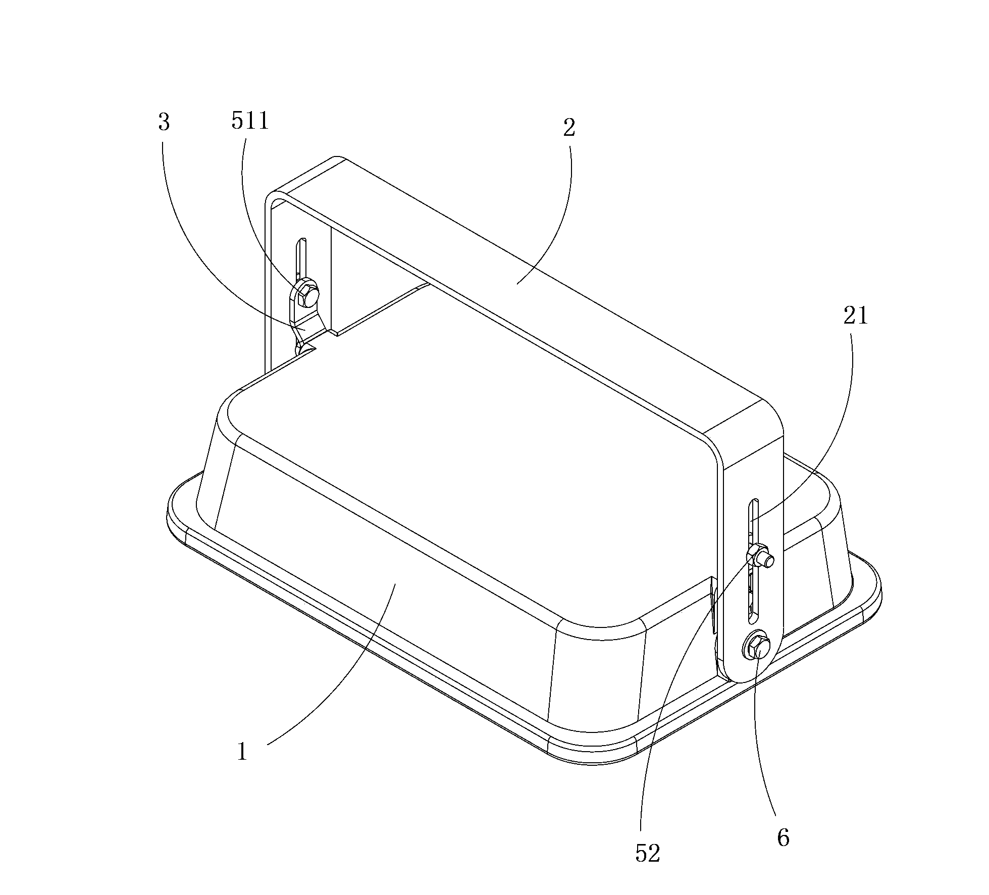
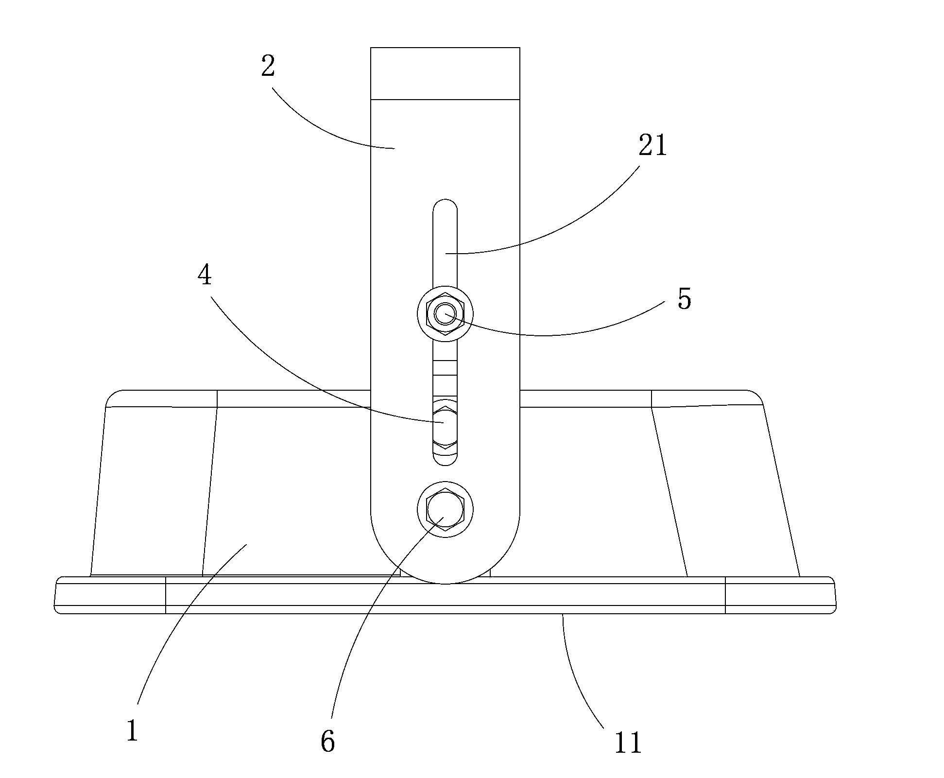
[0021] Such as figure 1 , figure 2 and Figure 5 As shown, the lamp installation structure provided by the embodiment of the present invention includes a lamp body 1 and a bracket 2, the bracket 2 is connected to the lamp body 1 through a first fastener 6, and the bracket 2 and the lamp body 1 Between them, there is a positioning block 3 that can prevent the relative rotation of the bracket 2 and the lamp body 1. One end of the positioning block 3 is connected to the lamp body 1 through the second fastener 4, and the other end is connected to the lamp body 1 through a locking member. 5 is conne...


PUM


Abstract

The invention is applicable to the technical field of lamp installation and discloses a lamp mounting structure. The lamp mounting structure comprises a lamp body and a support, wherein the support is connected with the lamp body in a hanging way, a positioning block capable of preventing the support and the lamp body from rotating relatively is arranged between the support and the lamp body, one end of the positioning block is fixed on the lamp body, while the other end of the positioning block is connected to the support through a locking member, and a sliding groove allowing the locking member to pass therethrough is formed on the support. The lamp mounting structure is characterized in that the positioning block is arranged between the support and the lamp body, one end of the positioning block is fixed on the lamp body, while the other end of the positioning block is connected to the support through the locking member, and the support is further fixedly connected with the lamp body, so that the connection of the lamp body and the support is secured in the three-point positioning way and relative rotation between the lamp body and the support is effectively prevented, and in the meantime, the sliding groove is formed on the support so that the positioning block is slidingly connected to the support and the connection points are continuous, and as a result, the illumination angle of the lamp is accurate and can be adjusted electrodelessly, and the illumination effect of the lamp is improved.

Description

technical field [0001] The invention belongs to the technical field of lamp installation, and in particular relates to a lamp installation structure. Background technique [0002] The traditional lamp installation structure includes a lamp body and a bracket, and the bracket is connected to the lamp body by screws. Such a structure is easy to install and can adjust the irradiation angle of the lamp, but it is easy to cause relative rotation between the lamp body and the bracket, so that the lamp Undesirable changes in the installation angle. [0003] In order to prevent relative rotation between the lamp body and the bracket, some improvements have been made on the traditional lamp installation structure in the prior art, mainly in two forms: one is to add a toothed plate between the bracket and the lamp body Structure, which adjusts the irradiation angle of the lamp and the connection between the locking bracket and the lamp body through the meshing of the internal teeth a...

Claims


Application Information

Patent Timeline
Patent Type & Authority Applications(China)
IPC IPC(8): F21V17/12F21V21/14F21V21/34
Inventor 周明杰刘先斌
Owner OCEANKING DONGGUAN LIGHTING TECH
Why Eureka
Try Eureka