Driving method of display panel

A display panel and driving method technology, applied to static indicators, instruments, etc., can solve problems such as uneven display and screen flickering

Pending Publication Date: 2020-10-23
SHENZHEN CHINA STAR OPTOELECTRONICS SEMICON DISPLAY TECH CO LTD
View PDF9 Cites 1 Cited by
  • Summary
  • Abstract
  • Description
  • Claims
  • Application Information

AI Technical Summary

Problems solved by technology

[0007] The purpose of the present invention is to provide a method for driving a display panel to solve the technical probl

Method used


Image

  • Driving method of display panel
  • Driving method of display panel
  • Driving method of display panel

Examples


Embodiment 1

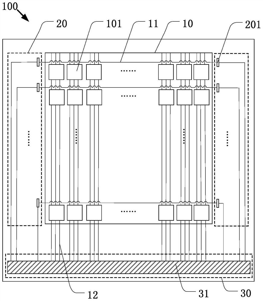
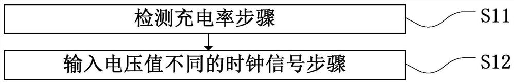
[0032] Embodiment 1 of the present invention is based on such as figure 1 In the display panel structure shown, the display area of ​​the display panel is provided with pixel units arranged in an array, and the pixel units are extended with scanning lines in rows. Such as image 3 As shown, a driving method of a display panel is provided in Embodiment 1, which includes steps:

[0033]S11. The step of detecting the charging rate is to detect the charging rate of each row of scanning lines in the display panel to be driven, and the charging rate is the charging time of the pixel units connected to the scanning lines in each row during each scan; and

[0034] S12. The step of inputting clock signals with different voltage values ​​is to input clock signals with different voltage values ​​corresponding to the charging rates of the scanning lines in each row. The scan lines are charged at the same rate.

[0035] In this embodiment, if the method of detecting the charging rate of...

Embodiment 2

[0041] Embodiment 2 of the present invention is based on such as figure 1 In the display panel structure shown, the display area of ​​the display panel is provided with pixel units arranged in an array, the pixel units are extended with scanning lines in rows, and each pixel unit is provided with a threshold voltage. Such as Figure 5 As shown, Embodiment 2 of the present invention provides a method for driving a display panel, which includes the steps of:

[0042] S21. The step of detecting the charging rate is to detect the charging rate of each row of scanning lines in the display panel to be driven, and the charging rate is the charging time of the pixel units connected to the scanning lines in each row during each scan; and

[0043] S22. The step of setting the threshold voltage of each row of pixel units, corresponding to the charging rate of each row of scanning lines, setting the threshold voltage of each row of pixel units connected to the scanning lines, the magnitu...

Embodiment 3

[0050] Embodiment 3 of the present invention is based on such as figure 1 In the display panel structure shown, the display area of ​​the display panel is provided with pixel units arranged in an array, and the pixel units are extended with scanning lines in rows, and each pixel unit is provided with a threshold voltage. Embodiment 3 of the present invention provides A method for driving a display panel, including the technical features of Embodiment 1 and Embodiment 2, so as to better realize that the charging rates of the scanning lines in each row are the same, specifically, as Figure 7 As shown, it includes the steps:

[0051] S31. The step of detecting the charging rate is to detect the charging rate of each row of scanning lines in the display panel to be driven, and the charging rate is the charging time of the pixel units connected to the scanning lines in each row during each scan; and

[0052] S32. Inputting clock signals with different voltage values ​​and setting...


PUM


Abstract

The invention provides a driving method of a display panel. The driving method of the display panel comprises the steps of detecting the charging rate, inputting clock signals with different voltage values and/or setting the threshold voltage of each row of pixel units. According to the invention, the charging rate of each row of scanning lines in the to-be-driven display panel is detected and then the clock signals with different input voltage values are adjusted and/or the threshold voltage of the pixel unit connected with each row of scanning lines is set corresponding to the charging rateof each row of scanning lines; the technical effect that the charging rates of the scanning lines in each row are the same is achieved, so that the charging difference of the display area in the display panel is eliminated, and the phenomena of image flickering and uneven display are avoided.

Description

technical field [0001] The present application relates to the field of display technology, and in particular to a method for driving a display panel. Background technique [0002] In the design of display panel products such as televisions (TVs), the large-scale metal wiring delay and process unevenness lead to differences in feed throughs at different positions or differences in film thickness, making the screen display of the entire panel Unevenness occurs, making the picture flicker (flicker) and 5nit uniformity is not good. [0003] see figure 1 As shown, it is a display panel 100 in the prior art, which is provided with a display area 10, a row driving area 20, and a binding area 30. The row driving area 20 is arranged around the display area 10, especially at the display area The binding area 30 is located on the left and right sides of the display area 10 and the row driving area 20 . Wherein, in the display area 10, there are pixel units 101 arranged in an array. ...

Claims


Application Information

Patent Timeline
IPC IPC(8): G09G3/20
CPCG09G3/20G09G2320/0247
Inventor 张伟伟
Owner SHENZHEN CHINA STAR OPTOELECTRONICS SEMICON DISPLAY TECH CO LTD
Why Eureka
Try Eureka