
A Combined Precision Control Buffer Device

A buffer device and a combined technology, applied in the direction of spring/shock absorber, low internal friction spring, shock absorber, etc., can solve the problems of limited buffer capacity of a single spring, inability to perform precise control, and large mechanical structure, etc., to achieve Improve the stability, improve the simplification of the machine structure, and reduce the impact force

Active Publication Date: 2022-05-31
河北凯恩机电设备有限公司
View PDF10 Cites 0 Cited by
  • Summary
  • Abstract
  • Description
  • Claims
  • Application Information

AI Technical Summary

Problems solved by technology

Commonly used cushioning parts are hydraulic cylinders or spring parts. Hydraulic cylinders need to be installed horizontally. The temperature and humidity of the working environment have requirements, and they have high requirements for safety, so their use in precision machinery is relatively limited; Low, high safety, but the buffer capacity of a single spring is limited, and precise control cannot be performed, and a single spring can only buffer in a single direction, and the simple superposition of the springs takes up a lot of space, resulting in a large mechanical structure. Therefore, for the above problems, it is necessary to propose further solutions

Method used


Image

  • A Combined Precision Control Buffer Device
  • A Combined Precision Control Buffer Device
  • A Combined Precision Control Buffer Device

Examples


Embodiment Construction

[0046] In the following description, many specific details are set forth in order to facilitate a full understanding of the present invention, but the present invention may also

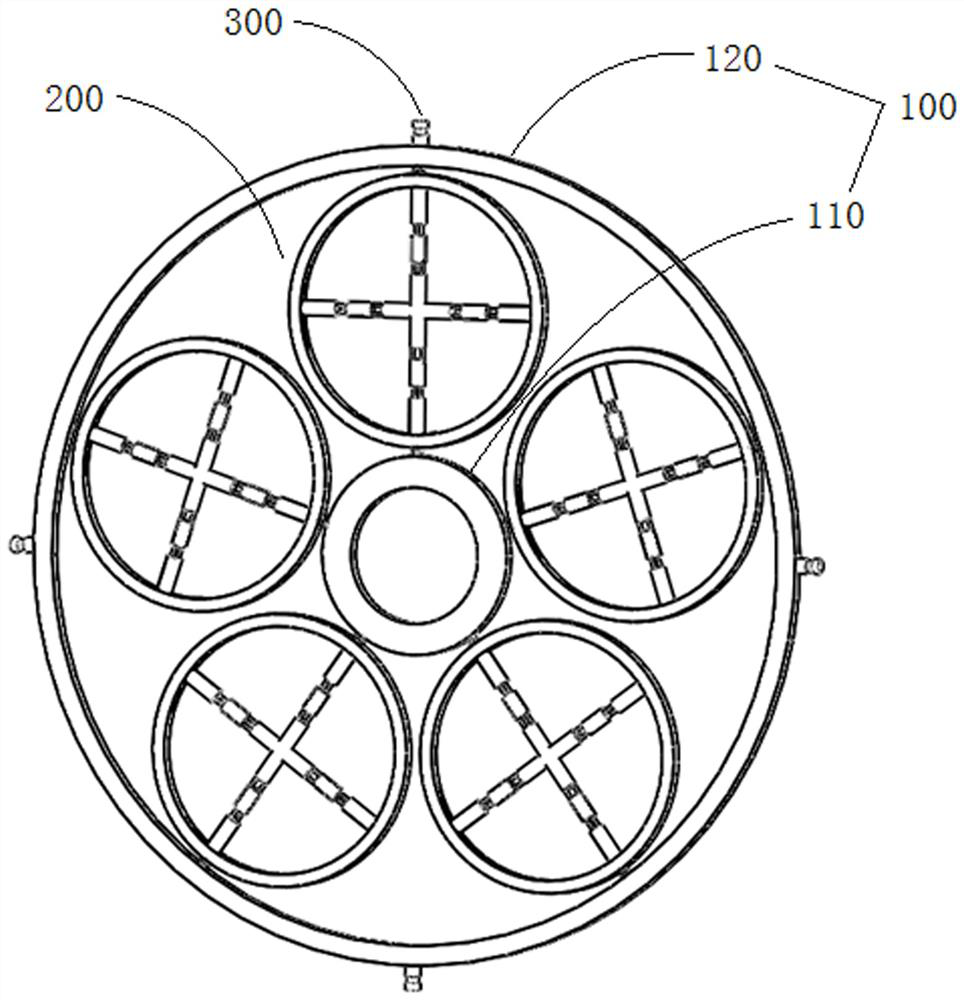
[0049] Fig. 1 shows a three-dimensional schematic diagram of the combined precise control buffer device.

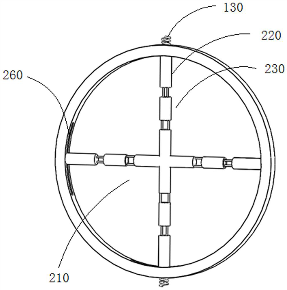
[0051] FIG. 2 shows a three-dimensional enlarged structural schematic diagram of the secondary control ring 200 in the combined precise control buffer device.

[0052] As shown in FIG. 2, the secondary control ring 200 is provided with at least one elastic mechanism 210, and the two ends of the elastic mechanism 210 are respectively

[0053] The inner wall of the secondary control ring 200 is preferably provided with a slide rail 260, and one end of the elastic mechanism 210 is slidably connected to the slide rail 260.

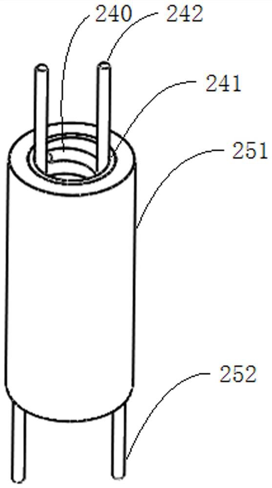
[0056] As shown in FIG. 3 and FIG. 4, the elastic element 230 includes an inner compression spring 240, an inner casing 241, an outer

[0057] In order to make the telescopic bufferi...


PUM


Abstract

The invention discloses a combined fine-control buffer device, which comprises a main control ring, a plurality of secondary control rings arranged inside the main control ring, and an installation block arranged outside the main control ring; Ring and outer ring, a plurality of secondary control rings are sequentially arranged between the inner ring and the outer ring, and connected with the main control ring; at least one elastic mechanism is arranged in the secondary control ring, and the two ends of the elastic mechanism respectively touch the secondary control ring The inner wall of the inner wall, the elastic mechanism includes connecting rods and elastic elements connected in sequence coaxially; an even number of mounting blocks are arranged along the outer periphery of the main control ring. The invention is suitable for the connection of machine parts, mechanisms and equipment in the same plane, and can effectively buffer the connection, protect the machine, prolong its service life, improve the stability and accuracy of operation and use, and through the regulation of the elastic mechanism It can not only provide precise buffer force to the machine, but also realize multi-directional differential buffer protection through different elastic mechanisms in different directions.

Description

A combined precision control buffer device technical field The present invention relates to the technical field of mechanical buffering, especially the connection places such as various machine parts, mechanisms and equipment. The buffering of the two, in particular, relates to a combined precise control buffering device. Background technique [0002] All kinds of mechanical equipment need to use a buffer, to weaken the larger impact force, provide protection for the mechanical equipment, Reduced damage, extended service life, and smooth operation. Commonly used buffer parts are hydraulic cylinders or spring parts. To be installed horizontally, the temperature and humidity of the working environment are required, and the safety requirements are high, so it is more suitable for use in precision machinery. Restricted; springs have a wide range of use, low environmental requirements and high safety, but a single spring has limited buffer capacity and cannot be accurately...

Claims


Application Information

Patent Timeline
Patent Type & Authority Patents(China)
IPC IPC(8): F16F3/04F16F7/00F16F15/02F16F15/067
CPCF16F7/00F16F3/04F16F15/067F16F15/02
Inventor 陈华安周苗何存
Owner 河北凯恩机电设备有限公司
Learn More