
Push bending equipment suitable for hollow profile bending and push bending method of push bending equipment

A top-bending and profile technology, applied in the field of machinery, can solve the problems of clamping deformation at the clamping point of the product, inconvenient product quality, etc., and achieve the effect of reducing elastic deformation and ensuring the bending effect.

Active Publication Date: 2020-10-30
SHANGHAI UNISON ALUMINUM PRODS
View PDF7 Cites 1 Cited by
  • Summary
  • Abstract
  • Description
  • Claims
  • Application Information

AI Technical Summary

Problems solved by technology

[0006] However, in the above-mentioned fixing method of the hollow profile, once the clamping force of the clamping part clamping the hollow profile is too large, it is easy to cause clamping deformation of the clamping part of the product, which is not convenient for ensuring product quality

Method used


Image

  • Push bending equipment suitable for hollow profile bending and push bending method of push bending equipment
  • Push bending equipment suitable for hollow profile bending and push bending method of push bending equipment

Examples


Embodiment Construction

[0048] The present invention will be further described below in conjunction with the accompanying drawings.

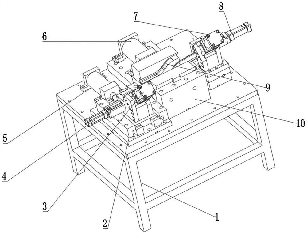
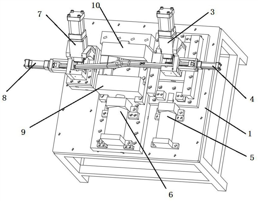
[0049] see figure 1 as well as figure 2 , is applicable to the top bending equipment for bending hollow profiles, including a main body of the top bending equipment, the main body of the top bending equipment includes a frame 1, a fixed forming block 10 is detachably installed on the frame, and a telescopic direction is detachably installed on the frame It is the main oil cylinder of the front and rear directions, and the piston rod of the main oil cylinder is detachably connected with a movable molding block 9, and the movable molding block and the fixed molding block are arranged front and back.

[0050] The left side oil cylinder clamping mechanism 3 that is used to fix the left end of the hollow profile can also be detachably installed on the frame 1. The left side oil cylinder clamping mechanism 3 includes a left support seat, and the left side on the left suppo...


PUM


Abstract

The invention relates to the technical field of machinery, in particular to push bending equipment suitable for hollow profile bending. The push bending equipment includes a machine frame. A movable forming block and a fixed forming block arranged in front and rear are detachably installed at the center of the machine frame, the movable forming block is detachably connected with a piston rod of amain oil cylinder, the telescopic direction of the piston rod is the forward-and-backward direction, a right oil cylinder clamping mechanism for fixing the right end of a workpiece is detachably installed on the right side of the machine frame, a left oil cylinder clamping mechanism for fixing the left end of the workpiece is further detachably installed on the left side of the machine frame, a guide rail is further detachably installed on the machine frame, the guide direction of the guide rail is the front-and-back direction, the left oil cylinder clamping mechanism is slidably connected with the guide rail, a left pushing oil cylinder for driving the left oil cylinder clamping mechanism to move front and back is further detachably installed on the left side of the machine frame, and a piston rod of the left pushing oil cylinder is detachably connected with the left oil cylinder clamping mechanism. According to the push bending equipment, by optimizing a traditional push bending mechanism, double-area pushing of the workpiece is achieved through a main oil cylinder and the left pushing oil cylinder, and the oil cylinder is used for compressing the material to reduce elastic deformation.

Description

technical field [0001] The invention relates to the field of mechanical technology, in particular to top bending equipment. Background technique [0002] Top bending is one of the processes in the processing of certain aluminum alloy workpieces. [0003] The bending method includes the direct bending method, that is, the aluminum alloy workpiece is bent around the fixed pillar, and the direct bending method has a large surface friction force during bending, which affects the appearance; and it will be deformed during bending, and manual bending There is no mold during the bending process, and the bending part is easy to sag, which reduces the strength of the steel pipe, and manual bending requires a lot of effort and high labor intensity. [0004] At present, there are also equipment for bending. For example, the Chinese patent application number 201610980489.2 discloses a hollow aluminum strip bending equipment and its use method. The device can bend the hollow aluminum st...

Claims


Application Information

Patent Timeline
IPC IPC(8): B21D9/08B21D9/16
CPCB21D9/08B21D9/16
Inventor 罗世兵王竹青
Owner SHANGHAI UNISON ALUMINUM PRODS
Learn More