Circularly polarized antenna for IOT device and IOT device with same

A circularly polarized antenna and equipment technology, applied in the field of wireless communication, can solve problems such as the influence of antenna signal receiving and receiving functions, and achieve the effect of enhancing signal receiving and receiving performance

Active Publication Date: 2020-11-03
BEIJING SMARTCHIP MICROELECTRONICS TECH COMPANY +1
View PDF7 Cites 0 Cited by
  • Summary
  • Abstract
  • Description
  • Claims
  • Application Information

AI Technical Summary

Problems solved by technology

Due to the diversity of IOT terminal nodes and the complexity of the use environment, it poses a lot of challenges to the manufacture of IOT equipment. Many IOT equipment need to adopt protective measur...

Method used


Image

  • Circularly polarized antenna for IOT device and IOT device with same
  • Circularly polarized antenna for IOT device and IOT device with same
  • Circularly polarized antenna for IOT device and IOT device with same

Examples


Embodiment 1

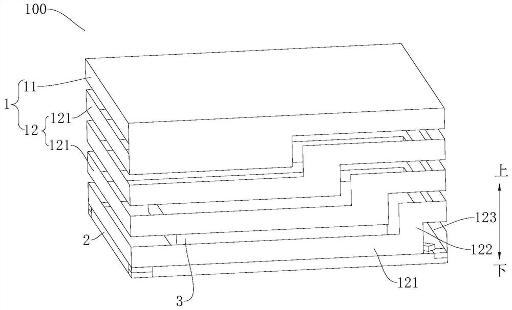
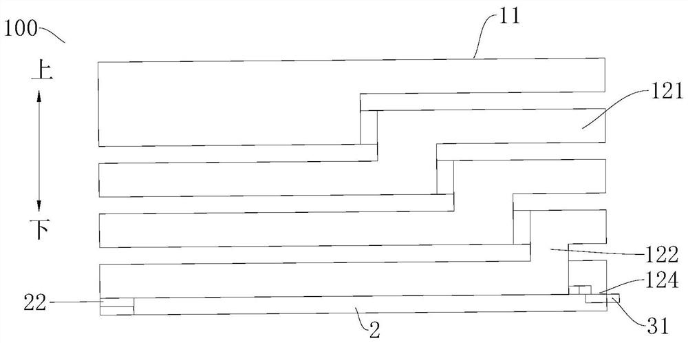
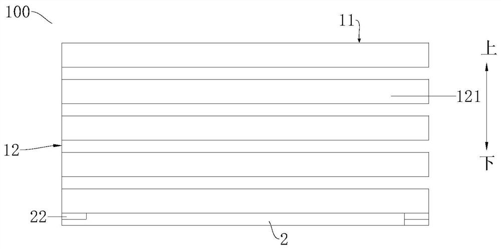
[0054] The IOT device 100 includes: a circularly polarized antenna 1 , a metal bottom cover 2 and a functional module 3 .

[0055] The circularly polarized antenna 1 is used for transmitting and receiving signals, and the circularly polarized antenna 1 includes: a first radiating part 11 and a second radiating part 12 . The first radiating part 11 can be formed as a square plate, the first radiating part 11 is formed as the top wall of the circularly polarized antenna 1, the second radiating part 12 spirally extends downward along the circumference of the first radiating part 11, and the second The radiation part 12 may include: a plurality of annular extension sections 121, in the direction from top to bottom, the plurality of annular extension sections 121 may be arranged at intervals, a gap is formed between two adjacent annular extension sections 121, each annular extension The sections 121 are all formed as a ring extending in a plane parallel to the bottom cover 2 and ha...

Embodiment 2

[0061] The IOT device 100 includes: a circularly polarized antenna 1 , a bottom cover 2 and a functional module 3 .

[0062] The circularly polarized antenna 1 is used for transmitting and receiving signals, and the circularly polarized antenna 1 includes: a first radiating part 11 and a second radiating part 12 . The first radiating part 11 can be formed as an annular plate body, and the first radiating part 11 is formed as the top wall of the circularly polarized antenna 1; the second radiating part 12 extends spirally downward along the circumference of the first radiating part 11, The second radiating part 12 may include: a plurality of annular extensions 121, and in the direction from top to bottom, the plurality of annular extensions 121 may be arranged at intervals, and each annular extension 121 is formed in a direction parallel to the bottom cover 2. A ring extending in a plane and having a gap 123, in the direction of the bottom cover 2 towards the first radiating pa...


PUM

PropertyMeasurementUnit
Thicknessaaaaaaaaaa

Abstract

The present invention discloses a circularly polarized antenna for an IOT device and an IOT device with the same. The circularly polarized antenna comprises a first radiation portion formed in a plateshape, and a second radiation portion; one end of the second radiation portion is connected to a peripheral edge of the first radiation portion, and in a thickness direction of the first radiation portion, the other end of the second radiation portion spirally extends downwards away from the first radiation portion along the circumferential direction of the first radiation portion. According to the circularly polarized antenna for the IOT equipment, the second radiation portion is connected with the first radiation portion , and the second radiation portion spirally extends downwards in the circumferential direction of the first radiation portion, so that the antenna forms the circularly polarized antenna with omnidirectional receiving capability, and the signal receiving and transmittingperformance of the antenna is enhanced.

Description

technical field [0001] The invention relates to the technical field of wireless communication, in particular to a circularly polarized antenna for an IOT device and an IOT device having the same. Background technique [0002] It is pointed out in related technologies that IOT (Internet of Things) technology, as an important application scenario in 5G technology, has begun to show more and more potential in various applications. Due to the diversity of IOT terminal nodes and the complexity of the use environment, it poses a lot of challenges to the manufacture of IOT equipment. Many IOT equipment need to adopt protective measures to prevent the environment from harming the equipment, and at the same time, it is necessary to avoid the protective measures adopted to damage the antenna. The signal sending and receiving function will be affected. Contents of the invention [0003] The present invention aims to solve at least one of the technical problems existing in the prior ...

Claims


Application Information

Patent Timeline
IPC IPC(8): H01Q1/36H01Q1/22H01Q1/50
CPCH01Q1/36H01Q1/22H01Q1/50
Inventor 杜君闻志国孙南庞振江李延李岩宋绍华郭飞
Owner BEIJING SMARTCHIP MICROELECTRONICS TECH COMPANY
Why Eureka
Try Eureka