
Electronic device

a technology of electronic devices and antenna modules, applied in the direction of antennas, antenna details, instruments, etc., can solve the problems of limited space and location of antenna modules, and achieve the effect of reducing the configuration space of electronic devices and improving the signal transceiving capability of the first antenna modul

Active Publication Date: 2022-10-04
COMPAL ELECTRONICS INC
View PDF17 Cites 0 Cited by
  • Summary
  • Abstract
  • Description
  • Claims
  • Application Information

AI Technical Summary

Benefits of technology

[0004]The invention provides an electronic device that may be properly provided with a plurality of antenna modules with good signal transceiving capability.
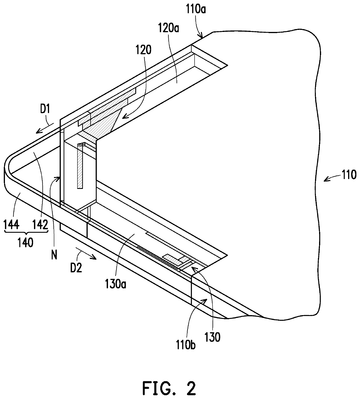
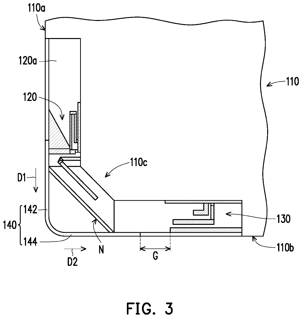
[0013]Based on the above, the electronic device of the invention is additionally provided with an electrically conductive structure connected to the first antenna module. The electrically conductive structure includes a first section and a second section respectively having different extending directions. Therefore, the electrically conductive structure may have suitable extending methods based on the signal transceiving requirements of the first antenna module and the structural design requirements of the device body, so as to improve the signal transceiving capability of the first antenna module in accordance with the structural design of the device body. In addition, the second section of the electrically conductive structure is extended toward the second antenna module and the two have a gap therebetween, so that the first antenna module, the second antenna module, and the electrically conductive structure may have a centralized configuration without affecting the antenna characteristics of the second antenna module. As a result, the configuration space of the electronic device is reduced.

Problems solved by technology

However, under the trend of a lean and thin design of notebook computers, the space and location of antenna modules are limited.
Therefore, how to properly configure a plurality of antenna modules with good signal transceiving capability in a limited configuration space and location is an important issue in this field.

Method used


Image

  • Electronic device
  • Electronic device
  • Electronic device

Examples


Embodiment Construction

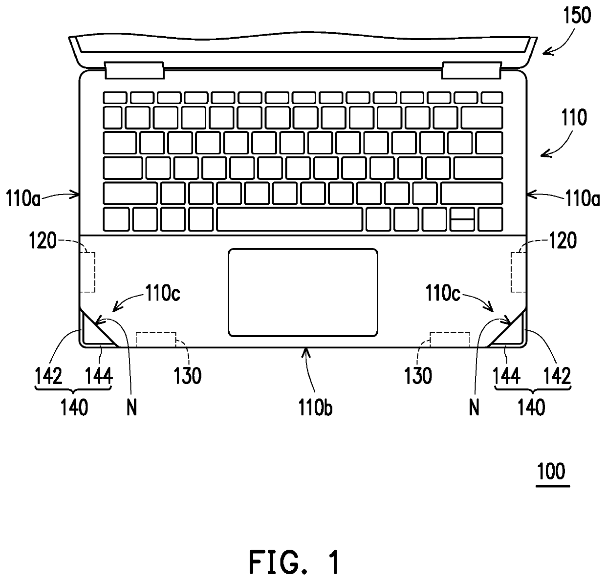
[0018]FIG. 1 is a partial top view of an electronic device of an embodiment of the invention. Referring to FIG. 1, an electronic device 100 of the present embodiment includes a device body 110, at least one first antenna module 120 (shown as two), at least one second antenna module 130 (shown as two), and at least one electrically conductive structure 140 (shown as two). The first antenna module 120 and the second antenna module 130 are disposed in the device body 110 and are, for example, different types of antenna modules that may include various antenna modules applied to long term evolution (LTE) wireless communication technology and various antenna modules applied to a multiple input multiple output (MIMO) wireless communication system, and the invention is not limited in this regard.

[0019]The electronic device 100 of the present embodiment is, for example, a notebook computer, and the device body 110 is, for example, a host of a notebook computer. The electronic device 100 fur...


PUM


Abstract

An electronic device including a device body, a first antenna module, a second antenna module, and an electrically conductive structure is provided. The first antenna module is disposed on the device body, and the second antenna module is disposed on the device body. The electrically conductive structure includes a first section and a second section, and the first section is connected between the first antenna module and the second section. The first section is extended along a first direction, the second section is extended toward the second antenna module along a second direction not parallel to the first direction, and the second section and the second antenna module have a gap therebetween.

Description

CROSS-REFERENCE TO RELATED APPLICATION[0001]This application claims the priority benefit of U.S. provisional application Ser. No. 62 / 838,316, filed on Apr. 25, 2019. The entirety of the above-mentioned patent application is hereby incorporated by reference herein and made a part of specification.FIELD OF THE INVENTION[0002]The invention relates to an electronic device, and particularly to an electronic device including an antenna.DESCRIPTION OF RELATED ART[0003]With the advancement of technology, the current public communication method has gradually changed to wireless communication, such as smart phones, tablet PCs and notebook computers with wireless internet access, etc., which are all in the field of wireless communication. Usually, wireless communication requires the use of antennas to transmit messages. In order to meet consumers' needs for wireless communication, some notebook computers are equipped with a plurality of antenna modules. However, under the trend of a lean and t...

Claims


Application Information

Patent Timeline
Patent Type & Authority Patents(United States)
IPC IPC(8): H01Q1/00G06F1/16H01Q1/22
CPCG06F1/1656G06F1/1616G06F1/1637H01Q1/2266G06F1/1698
Inventor CHEN, I-LUNGYEH, WANG-HUNGHUNG, HSIAO-CHINGLEE, LI-CHUNLIU, SHIH-CHIALIN, KUN-RONG
Owner COMPAL ELECTRONICS INC
Learn More