A planting device for planting fluorescent microfilaments on airfoil surfaces

A technology of airfoil and microwire, which is applied in the field of wind tunnel test, can solve the problems of cumbersome operation and infirmity, and achieve the effect of simplifying complicated and cumbersome, stable wire, and simplifying the cumbersome installation

Active Publication Date: 2021-09-28
NORTHWESTERN POLYTECHNICAL UNIV
View PDF0 Cites 0 Cited by
  • Summary
  • Abstract
  • Description
  • Claims
  • Application Information

AI Technical Summary

Problems solved by technology

[0004] The purpose of the present invention is to provide a planting device for planting fluorescent microfilaments on the airfoil surface, so as to solve the problems of cumbersome operation and infirmity of the existing copper tube planting silk thread method

Method used


Image

  • A planting device for planting fluorescent microfilaments on airfoil surfaces
  • A planting device for planting fluorescent microfilaments on airfoil surfaces
  • A planting device for planting fluorescent microfilaments on airfoil surfaces

Examples


Embodiment Construction

[0021] The present invention will be described in detail below in conjunction with the accompanying drawings and specific embodiments.

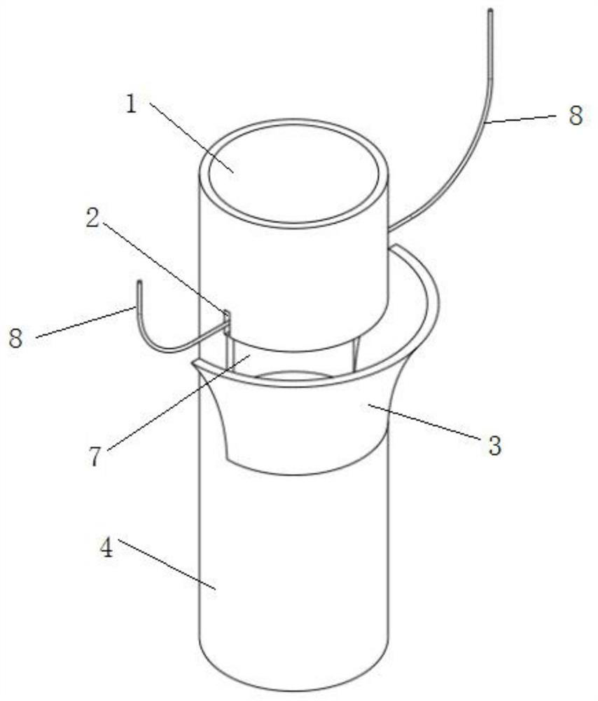
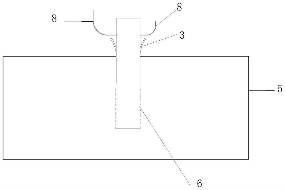
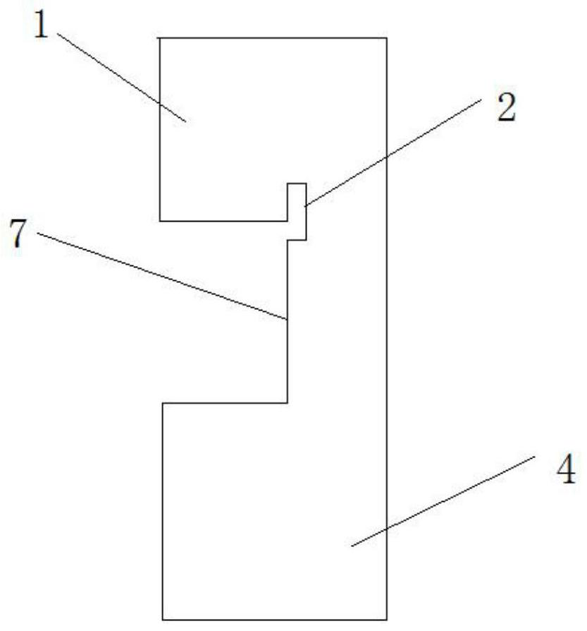
[0022] Such as figure 1 As shown, the present invention provides a planting device for planting fluorescent microfilaments on the airfoil surface. In some embodiments, it includes: a copper tube, two wire clamping slots 2 and an opening 7 . Wherein, the copper tube is divided into upper and lower parts, the upper part is a hollow cylinder 1, and the lower part is a solid cylinder 4, and the inside of the hollow cylinder 1 is used for injecting the adhesive for fixing the wire and the copper tube. The outer wall of the hollow cylinder 1 is provided with two wire-holding grooves 2, the direction of the two wire-holding grooves 2 is the same as the axial direction of the hollow cylinder 1, the two wire-holding grooves 2 are arranged at intervals, and the size of the wire-holding grooves 2 is different. The limit is usually selected according to...


PUM


Abstract

The invention discloses a planting device for planting fluorescent filaments on the surface of an airfoil, comprising: a copper tube, the upper part of which is a hollow cylinder, and the lower part is a solid cylinder; the inside of the hollow cylinder is used for injecting adhesive ; Two wire-holding grooves are two bar-shaped grooves opened on the outer wall of the hollow cylinder, which are arranged at intervals along the axis of the hollow cylinder; one opening is arranged on the outer wall of the hollow cylinder and is located between the two wire-holding grooves The space is used to connect the bottom ends of the two wire holding grooves; the opening is used to provide the entrance for the wire to enter the two wire holding grooves, so that the two ends of the wire thread are hung in the two wire holding grooves respectively. The problem of cumbersome operation and infirmity of the existing copper pipe planting silk thread method is solved.

Description

technical field [0001] The invention belongs to the technical field of wind tunnel tests, and in particular relates to a planting device for planting fluorescent filaments on the surface of an airfoil. Background technique [0002] Fluorescent microfilament flow display technology is widely used in various wind tunnels and field tests due to its simple operation, wide application range and small impact on the flow field. This technology is a newly developed method of observing the surface flow field of the test model on the basis of the conventional silk flow display technology. Synthetic fibers containing fluorescent substances are used to make fluorescent microfilaments, and then fixed on the surface of the test model. The diameter of the wire made of this fiber is extremely small, which can ensure the accuracy and authenticity of the flow field near the model to a large extent, and greatly reduce the influence on the surface flow field of the test model. It is very diffi...

Claims


Application Information

Patent Timeline
Patent Type & Authority Patents(China)
IPC IPC(8): G01M9/02G01M9/04G01M9/06
CPCG01M9/02G01M9/04G01M9/067
Inventor 惠增宏王景龙邓磊李小兵郭乐
Owner NORTHWESTERN POLYTECHNICAL UNIV
Why Eureka
Try Eureka