A rim and wheel with asymmetrical design of rims on both sides

An asymmetrical and rim-based technology, which is applied to rims, vehicle parts, transportation and packaging, etc., can solve the problems of reduced tire service life, tire partial wear, and large tire wear, so as to eliminate tire partial wear, uniform force, The effect of prolonging the service life

Active Publication Date: 2022-08-05
东风汽车底盘系统有限公司
View PDF11 Cites 0 Cited by
  • Summary
  • Abstract
  • Description
  • Claims
  • Application Information

AI Technical Summary

Problems solved by technology

[0004] However, after combining the spokes and the rim into a wheel, the rigidity of the proximal rim with the spoke support end will be greater than that of the far end rim without the spoke support end, resulting in a difference in the stiffness of the rim at both ends of the wheel
The difference in the stiffness of the rims on both sides of the wheel makes the strains of the rims on both sides of the wheel different during driving, which makes the force on both sides of the tire uneven during normal driving, resulting in great wear of the tire at the rim where the ground faces the spoke support end. The wear of the tire at the rim of the spoke support end is small, which causes partial wear of the tire, which in turn causes abnormal vibration of the vehicle, affects the handling performance of the car, and reduces the service life of the tire

Method used


Image

  • A rim and wheel with asymmetrical design of rims on both sides
  • A rim and wheel with asymmetrical design of rims on both sides
  • A rim and wheel with asymmetrical design of rims on both sides

Examples


Embodiment 1

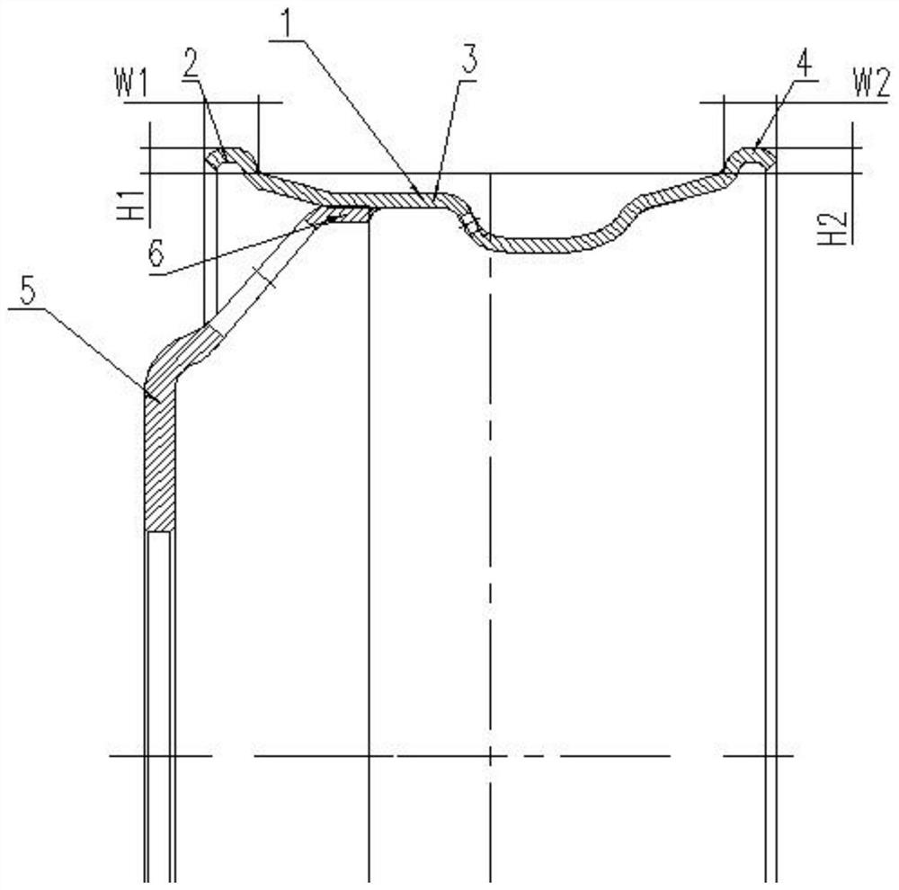
[0029] figure 2 , W1 is the width of the proximal rim 2, that is, the horizontal distance from the connection between the proximal rim 2 and the intermediate portion 3 to the end of the proximal rim 2; H1 is the height of the proximal rim 2, that is, the close The vertical distance from the junction of the end rim 2 and the middle part 3 to the top of the proximal rim 2 .

[0030] W2 is the width of the distal rim 4, that is, the horizontal distance from the connection between the distal rim 4 and the intermediate portion 3 to the end of the distal rim 4; H2 is the height of the distal rim 4, that is, the distal rim The vertical distance from the junction of the rim 4 to the intermediate portion 3 to the top of the distal rim 4 .

[0031] like figure 2 As shown, the nominal diameter and hook length of the proximal rim 2 and the distal rim 4 are equal, but the width W2 of the distal rim 4 is 105%-130% of the width W1 of the proximal rim 2, and the distal The height H2 of t...

Embodiment 2

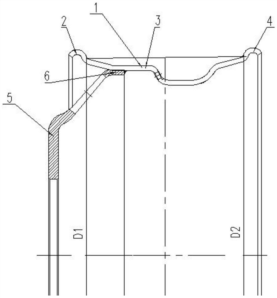
[0033] image 3 , D1 is the calibrated diameter of the proximal rim 2, that is, the outer diameter of the connection between the proximal rim 2 and the middle part 3; D2 is the calibrated diameter of the distal rim 4, that is, the distal rim 4 and the middle part 3 outside diameter of the junction.

[0034] like image 3 As shown, the width, height and hook length of the proximal rim 2 and the distal rim 4 are equal, but the nominal diameter D2 of the distal rim 4 is 1-2 mm larger than the nominal diameter D1 of the proximal rim 2 . Taking a 22.5X9.00 15° deep groove rim as an example, the calibrated diameter D2 of the distal rim 4 is set to Φ573.0±0.4mm, and the calibrated diameter D1 of the proximal rim 2 is set to Φ571.5±0.4mm.

Embodiment 3

[0036] Figure 4 , L1 is the hook length of the proximal rim 2, the vertical distance from the end of the proximal rim 2 to the top of the proximal rim 2; L2 is the hook length of the distal rim 4, the distal rim The vertical distance from the end of the rim 4 to the top of the distal rim 4 .

[0037] like Figure 4 As shown, the width, height and nominal diameter of the proximal rim 2 and the distal rim 4 are equal, but the hook length L2 of the distal rim 4 is 140%-180% of the hook length L1 of the proximal rim 2 %. Taking a 22.5X9.00 rim with a 15° deep groove as an example, the hook length L2 of the distal rim 4 is set to 17 mm, and the hook length L1 of the proximal rim 2 is set to 10 mm.


PUM


Abstract

The invention relates to a rim and a wheel with asymmetric design of rims on both sides, comprising a proximal rim, a middle part and a distal rim; the proximal rim and the distal rim are respectively arranged in the middle Both ends of the rim, and the proximal rim and the distal rim adopt asymmetric design, so that the rigidity of the distal rim is greater than that of the proximal rim; The rigidity of the distal rim is greater than that of the proximal rim. During use, the rigidity of the proximal rim increases due to the support of the spokes, so that the rigidity of the rims on both sides is consistent. In this way, the tire exerts an even force during the driving process, which can eliminate the eccentric tire wear caused by the different stiffness of the two ends of the traditional wheel, and prolong the service life of the wheel.

Description

technical field [0001] The invention relates to the technical field of wheels, in particular to a rim and a wheel with asymmetrical design of rims on both sides. Background technique [0002] The wheel is composed of a rim and a spoke. The open end of the spoke is assembled with the inner side of the mounting spoke surface of the rim, and then the rim and the spoke are formed into a whole by welding. [0003] Bead seats and rims are arranged on both ends of the rim, and the bead seats and the rims enable the tire to be well mounted on the wheel. like figure 1 As shown, in order to improve the service life of the tire, the rims on both sides of the existing rim are symmetrically designed, so that the rigidity of the rims on both sides of the rim is consistent. For example, the invention patent with the application number of CN201720251743.5 proposes a steel rim for a small agricultural vehicle, including a rim and a spoke, the rim includes a bead seat and a rim, the rim is ...

Claims


Application Information

Patent Timeline
Patent Type & Authority Patents(China)
IPC IPC(8): B60B21/02
CPCB60B21/023
Inventor 胡飞杨荣王峰余海洋彭峻潘小雨
Owner 东风汽车底盘系统有限公司
Why Eureka
Try Eureka