
Swing check valve

A check valve and swing-type technology, applied in valve details, control valves, valve devices, etc., can solve problems such as reduced service life, valve damage, and high impact force on the sealing surface of the valve seat, so as to prevent damage to the sealing surface, Avoid rapid closing and prevent water hammer effect

Active Publication Date: 2020-12-15
浙江阿尔法阀门有限公司
View PDF5 Cites 0 Cited by
  • Summary
  • Abstract
  • Description
  • Claims
  • Application Information

AI Technical Summary

Problems solved by technology

The following problems often occur during the use of existing swing check valves: when the check valve disc rotates around the pin shaft and closes, due to the fast closing speed, the impact of the disc sealing surface on the sealing surface of the valve seat will occur. If the force is too large, it is easy to damage the sealing surface, so that the check valve cannot be effectively closed, and the service life is reduced; at the same time, when the check valve disc is closed quickly, it is easy to generate water hammer, resulting in damage to the valve and other harmful situations.

Method used


Image

  • Swing check valve
  • Swing check valve
  • Swing check valve

Examples


Embodiment Construction

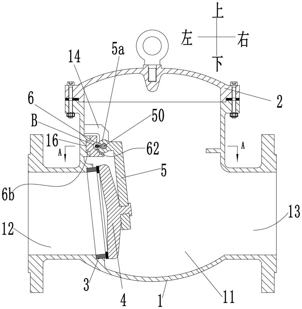
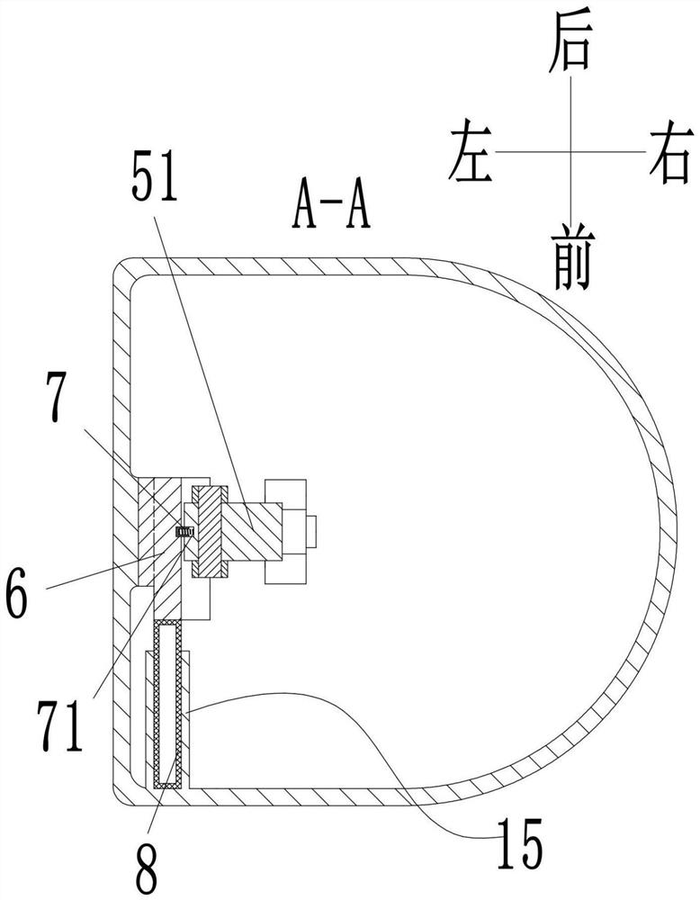
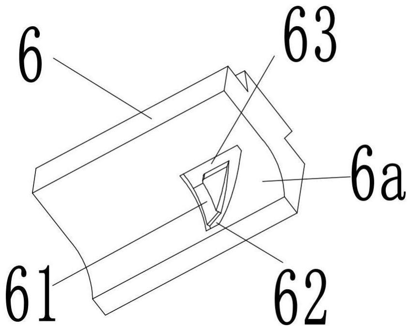
[0019] see Figure 1-5 As shown, a swing check valve includes a valve body 1, the valve body 1 is provided with a valve chamber 11, and the side of the valve body 1 is provided with an inlet pipe 12 and an outlet pipe communicated with the valve chamber 11. 13. The upper opening of the valve cavity 11 is fixed with a bonnet 2, and the left side wall of the valve cavity 11 is provided with two struts 14 above the inlet pipe 12, and the two struts 14 are vertical to the A horizontal shaft 50 is arranged in the axial direction of the inlet pipe 12, and a shaft sleeve 5a is rotatably connected to the shaft shaft 50, and a rocker 5 is extended outside the shaft sleeve 5a, and the rocker 5 is positioned away from the support bar. 14 is fixedly installed with a disc 4 for controlling the on-off of the inlet pipe 12; the left side wall of the valve cavity 11 is slidably connected with a pressure block 6 along the axial direction of the shaft 50 under the support rod 14, and the valve ...


PUM


Abstract

The invention discloses a swing check valve. The swing check valve comprises a valve body, a valve cavity is formed in the valve body, and an inlet pipe and an outlet pipe which communicate with the valve cavity are arranged on the side face of the valve body; and a valve cover is fixedly installed at an upper opening of the valve cavity. The swing check valve is characterized in that two supporting rods are arranged at the position, above the inlet pipe, of the left side wall of the valve cavity; a horizontal shaft rod is arranged between the two supporting rods in the axial direction perpendicular to the inlet pipe; a shaft sleeve is rotationally connected to the shaft rod; a rocker is arranged on the outer side of the shaft sleeve in an extending mode; a valve clack for controlling theinlet pipe to be through or blocked is fixedly installed at one end, away from the supporting rods, of the rocker; a pressing block is slidably connected to the position,below the supporting rods, ofthe left side wall of the valve cavity in the axial direction of the shaft rod; an elastic piece used for forcing the pressing block to move towards the rear side wall of the valve cavity is arrangedat the position,at one end of the pressing block, of the front side wall of the valve cavity; and a transmission assembly connected with the shaft sleeve is arranged in the pressing block. The swing check valve is reasonable in structure and reliable in use, the valve clack can be opened quickly and closed slowly, and impact is prevented.

Description

technical field [0001] The invention belongs to the technical field of pipeline valves, in particular to a swing check valve. Background technique [0002] The check valve is a valve commonly used in the pipeline system, which is used to connect and check the fluid medium in the pipeline system. The existing swing check valve mainly includes a valve body, a valve seat and a check disc. And it is installed in the inner cavity of the valve by the pin shaft. When the medium enters the inner cavity of the valve from the inlet side of the valve (the medium flows forward), the medium pushes the check valve disc to rotate around the pin shaft to open. When the medium enters the inner cavity of the valve from the outlet side of the valve When (the medium flows in the opposite direction), the check disc rotates around the pin to close the valve port. The following problems often occur during the use of existing swing check valves: when the check valve disc rotates around the pin sh...

Claims


Application Information

Patent Timeline
IPC IPC(8): F16K15/03F16K47/02F16K47/00
CPCF16K15/033F16K47/023F16K47/00
Inventor 武芳李辉洪德朋
Owner 浙江阿尔法阀门有限公司
Learn More