Swing check valve

A check valve, swing-type technology, applied in the direction of valve details, control valves, valve devices, etc., can solve the problems of reduced service life, valve damage, easy to damage the sealing surface, etc., to prevent damage to the sealing surface and prolong the service life , Ease of use

Inactive Publication Date: 2021-02-12
段井胜
View PDF0 Cites 1 Cited by
  • Summary
  • Abstract
  • Description
  • Claims
  • Application Information

AI Technical Summary

Problems solved by technology

[0002] The check valve is a valve commonly used in the pipeline system, which is used to connect and check the fluid medium in the pipeline system. The existing swing check valve mainly includes a valve body, a valve seat and a valve disc. The valve seat is fixed in the flow channel of the valve body and has a seat sealing surface. The valve disc is installed in the inner cavity of the valve body by a pin shaft and has a valve disc sealing surface. When the medium enters the inner cavity of the valve body from the inlet flow channel of the valve body, the medium Push the disc to rotate around the pin shaft to open the valve port. When the medium enters the inner cavity of the valve body from the outlet channel of the valve body, the disc rotates around the pin shaft to close the valve port. There are the following problems: because the closing speed of the valve disc is too fast when it rotates around the pin shaft, the impact force of the valve disc sealing surface on the sealing surface of the valve seat will be too large, and the sealing surface will be easily damaged, so that the check valve cannot be effectively closed, reducing Its service life; at the same time, the valve disc is prone to water hammer when it is closed quickly, resulting in damage to the valve and other harmful situations.

Method used


Image

  • Swing check valve
  • Swing check valve
  • Swing check valve

Examples


Embodiment Construction

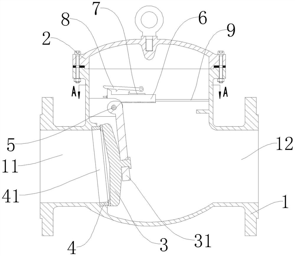
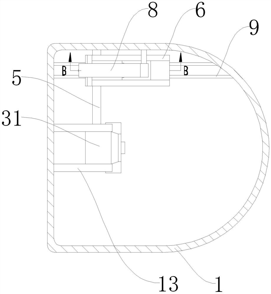
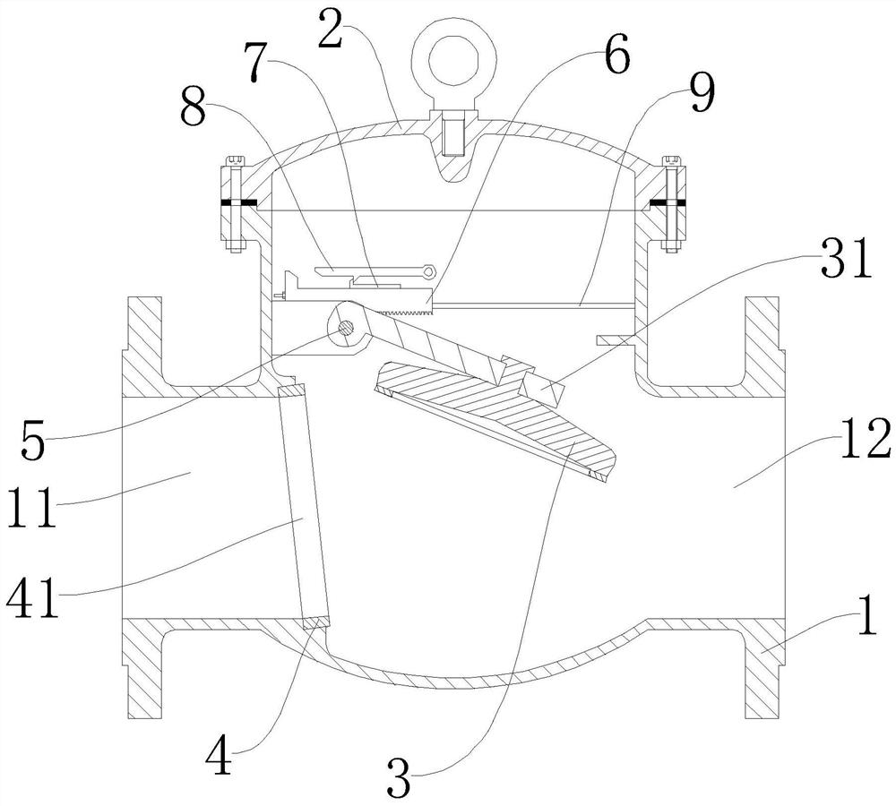
[0021] The following will clearly and completely describe the technical solutions in the embodiments of the present invention with reference to the accompanying drawings in the embodiments of the present invention. Obviously, the described embodiments are only some, not all, embodiments of the present invention. Based on the embodiments of the present invention, all other embodiments obtained by persons of ordinary skill in the art without making creative efforts belong to the protection scope of the present invention.

[0022] It should be noted that when a component is said to be "mounted on" another component, it may be directly on the other component or there may be an intervening component. When a component is said to be "set on" another component, it may be set directly on the other component or there may be an intervening component at the same time. When a component is said to be "fixed" to another component, it may be directly fixed to the other component or there may ...


PUM


Abstract

The invention relates to a swing check valve. The swing check valve comprises a valve body and a valve deck arranged at the upper end of the middle of the valve body, wherein an inlet flow channel andan outlet flow channel are formed in the valve body, a valve seat is arranged at the position, located at the outlet end of the inlet flow channel, in the valve body, a fluid channel communicating with the inlet flow channel is formed in the valve seat, a valve clack matching with the valve seat is arranged in the valve body, and the swing check valve further comprises a speed reducing mechanismused for reducing the closing speed of the valve clack when the valve clack is closed. The swing check valve has the beneficial effects that by arranging the speed reducing mechanism, the valve clackis prevented from being closed quickly when a medium flows reversely, so that the phenomenon that a sealing surface is damaged due to too large impact force is prevented, the service life of the checkvalve can be prolonged, the water hammer phenomenon can be prevented, the check valve is protected, and the swing check valve is prevented from being suffering other harmful conditions such as damage.

Description

technical field [0001] The invention belongs to the technical field of check valves, in particular to a swing check valve. Background technique [0002] The check valve is a valve commonly used in the pipeline system, which is used to connect and check the fluid medium in the pipeline system. The existing swing check valve mainly includes a valve body, a valve seat and a valve disc. The valve seat is fixed in the flow channel of the valve body and has a seat sealing surface. The valve disc is installed in the inner cavity of the valve body by a pin shaft and has a valve disc sealing surface. When the medium enters the inner cavity of the valve body from the inlet flow channel of the valve body, the medium Push the disc to rotate around the pin shaft to open the valve port. When the medium enters the inner cavity of the valve body from the outlet channel of the valve body, the disc rotates around the pin shaft to close the valve port. There are the following problems: becaus...

Claims


Application Information

Patent Timeline
Patent Type & Authority Applications(China)
IPC IPC(8): F16K15/03F16K47/02
CPCF16K15/033F16K47/023
Inventor 段井胜刘秋燕
Owner 段井胜
Why Eureka
Try Eureka