Multi-energy storage circulating generator set

A technology for circulating generator sets and generators, applied in generators/motors, photovoltaic power generation, electromechanical devices, etc., can solve the problems of troublesome management, waste of land resources, long construction period, etc., and achieve the effect of improving production and living environment

Pending Publication Date: 2020-12-18
董四清
View PDF0 Cites 0 Cited by
  • Summary
  • Abstract
  • Description
  • Claims
  • Application Information

AI Technical Summary

Problems solved by technology

[0003] Existing power generation technology or energy storage technology or energy storage power generation equipment, whether it is power generation equipment or energy storage power generation equipment, either causes waste of land resources, or causes damage to the ecological environment, or has certain hidden dangers in safety, or construction period It is difficult to operate and manage and the cost of management and maintenance is high, or due to the influence of resource layout or geographical conditions or the distribution of natural environmental resources, energy conservation and environmental protection, or backward energy storage equipment and other conditions, it is impossible to meet and realize the most ideal energy storage according to actual needs. Power generation effect and better generation of economic benefits and social public benefits

Method used


Image

  • Multi-energy storage circulating generator set
  • Multi-energy storage circulating generator set
  • Multi-energy storage circulating generator set

Examples


Embodiment 1

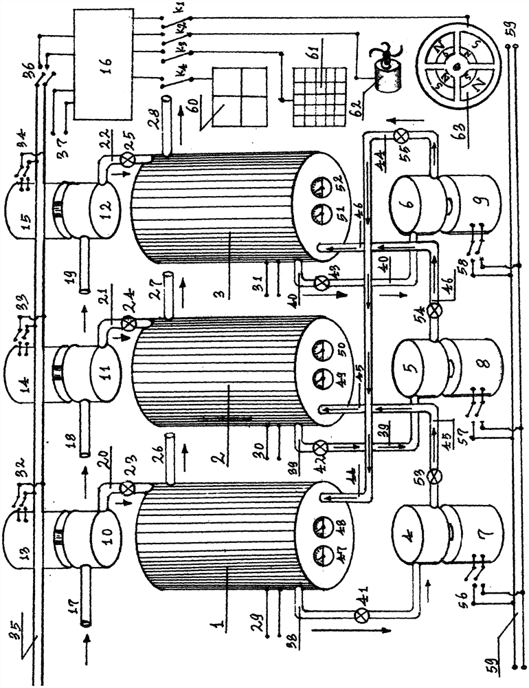
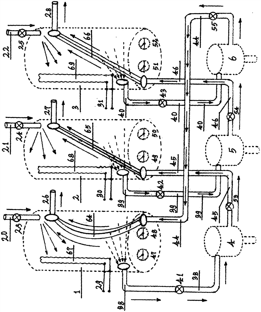
[0036] Embodiment 1: The temperature-insulated and pressure-resistant tank (1, 2, 3) of the present invention is respectively connected with the air pump (10, 11, 12) through the air pump outlet (20, 21, 22) and through the air pump outlet control valve (23 . Shafts are connected, and air pumps (10, 11, 12) are respectively provided with air pump inlets (17, 18, 19); 6) Connect the air pump exhaust control pipes (38, 39, 40) through the air pump exhaust control valves (41, 42, 43), and the air pumps (4, 5, 6) are respectively connected to the generators (7, 8 , 9) are coaxially connected, and air pumps (4, 5, 6) are respectively provided with air pump exhaust pipe control valves (53, 54, 55); air pressure pumps (4, 5, 6) are connected with tank inlet pipes ( 44, 45, 46) are connected, and enter the temperature insulation and pressure tank (1, 2, 3) to communicate with the pressure heat dissipation pipe (64, 65, 66) and the air release pipe (26, 27, 28); the electric heater wi...

Embodiment 2

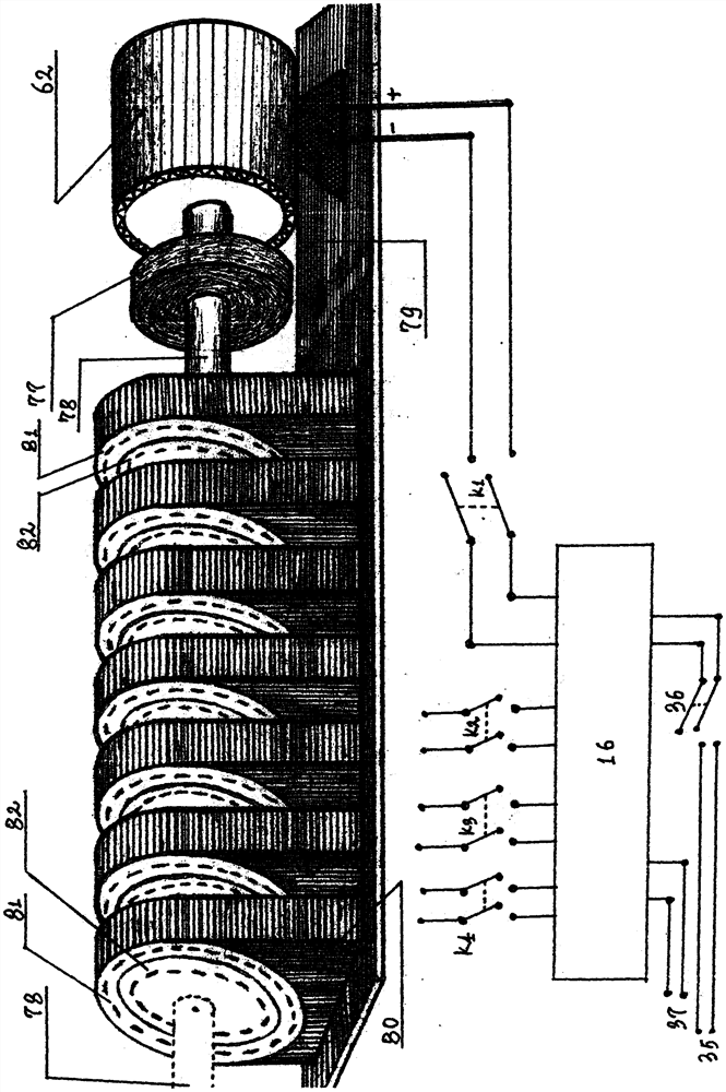
[0037] Embodiment 2: the inverter (16) of the present invention is provided with 50Hz AC output line (37), the state network line switch (36) is connected in parallel with the state network line (35), and the output number line (37) is connected with the electric heater lead respectively (29, 30, 31) are connected in parallel, and the inverter (16) is provided with four wide-voltage DC input switches (K1, K2, K3, K4), and the switches (K1, K2, K3, K4) are respectively It is connected in parallel with the magnetoelectric component (63), the wind generator (62), the photovoltaic panel (61) and the thermoelectric panel (60).

Embodiment 3

[0038] Embodiment 3: The power output lines (56, 57, 58) of the generators (7, 8, 9) of the present invention are respectively connected in parallel with the bus line (59).


PUM


Abstract

The invention discloses a multi-energy-in-one multi-energy storage circulating generator set. The generator set comprises a heat-insulation pressure-resistant tank, a generator, a pneumatic pump, a motor, an inflator pump, an electric heater, a photovoltaic panel, a temperature difference power generation panel, an inverter, a wind-driven generator and a magnetoelectric generator, wherein the electric heater and a radiating pipe are arranged in the heat-insulation pressure-resistant tank, and media in the tank are air and distilled water; an electric heater wire, a barometer, a thermometer, anair inlet pipe, an exhaust pipe and a deflation pipe are arranged on the heat-insulation pressure-resistant tank, and an inflation pipe is connected with the inflator pump; the exhaust pipe is connected with the pneumatic pump; the deflation pipe is connected with an inverted Y-shaped radiating pipe orifice; and output and input lines of the inverter are connected with a state grid, the motor, the generator, the temperature difference power generation panel, the photovoltaic panel, the wind-driven generator and a magnetic unit in parallel. The pipelines outside the heat-insulation pressure-resistant tank are made of pressure resistance and heat preservation materials, the pipelines inside the tank are made of pressure resistance and heat dissipation materials, the inflator pump is coaxially connected with the motor, and the pneumatic pump is coaxially connected with the generator. The generator set is scientific and reasonable in design, wide in application, zero in emission, energy-saving, environment-friendly, safe and efficient.

Description

Technical field: [0001] The present invention belongs to the multi-energy energy storage cycle generating set which collects and comprehensively utilizes various energy sources together, and specifically relates to a multi-energy energy storage cycle generating set which is designed by utilizing the excess power resources and natural energy of the national grid at night and applying modern scientific and technological means. . [0002] technical background: [0003] Existing power generation technology or energy storage technology or energy storage power generation equipment, whether it is power generation equipment or energy storage power generation equipment, either causes waste of land resources, or causes damage to the ecological environment, or has certain hidden dangers in safety, or construction period It is difficult to operate and manage and the cost of management and maintenance is high, or it is limited by resource layout or geographical conditions or the distribut...

Claims


Application Information

Patent Timeline
Patent Type & Authority Applications(China)
IPC IPC(8): H02K53/00H02S10/10H02S10/12H02N11/00
CPCH02K53/00H02N11/002H02S10/10H02S10/12Y02E10/50
Inventor 董四清
Owner 董四清
Why Eureka
Try Eureka