
Remote centralized monitoring system and method for remote sensing satellite ground station network

A technology for centralized monitoring and remote sensing satellites, applied in the field of remote sensing satellite reception, it can solve the problems of information dispersion, unfavorable operation and management of the station network center, and inability to customize remote client information, and achieve the effect of rapid expansion capability.

Active Publication Date: 2020-12-25
AEROSPACE INFORMATION RES INST CAS
View PDF7 Cites 0 Cited by
  • Summary
  • Abstract
  • Description
  • Claims
  • Application Information

AI Technical Summary

Problems solved by technology

[0004] 1. Each sub-system of the ground station needs to be equipped with independent monitoring equipment to deploy remote clients, resulting in the need to deploy hundreds of sets of monitoring equipment in the station network center, which seriously wastes equipment resources and is very unfavorable for the operation and management of the station network center;
[0005] 2. The information reported by the remote client cannot be customized. On the one hand, it occupies valuable network bandwidth of each site and the center of the station network. On the other hand, the various status information reported has not been effectively classified and organized. Operation and maintenance personnel quickly discover and locate faults;
[0006] 3. The data and information of each ground station cannot be collected, stored and managed in a unified manner, and the information is scattered, so it is impossible to realize remote centralized monitoring of the status of all ground stations. It is very inconvenient for operation and maintenance personnel to grasp the status of each station in the remote sensing satellite data receiving station network Overall operating situation

Method used


Image

  • Remote centralized monitoring system and method for remote sensing satellite ground station network
  • Remote centralized monitoring system and method for remote sensing satellite ground station network
  • Remote centralized monitoring system and method for remote sensing satellite ground station network

Examples


Embodiment Construction

[0049] In the description of the present invention, it should be noted that unless otherwise specified and limited, the terms "installation", "connection" and "connection" should be understood in a broad sense, for example, it can be a fixed connection or a detachable connection. Connected, or integrally connected; it may be mechanically connected or electrically connected; it may be directly connected or indirectly connected through an intermediary, and it may be the internal communication of two components. Those of ordinary skill in the art can understand the specific meanings of the above terms in the present invention in specific situations.

[0050] An embodiment of the present invention provides a remote centralized monitoring system for remote sensing satellite ground station network, including sub-system level communication components, station level communication components and station network level communication components; each level of communication components inclu...


PUM


Abstract

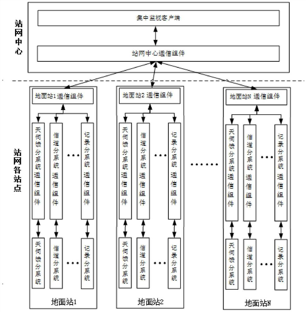
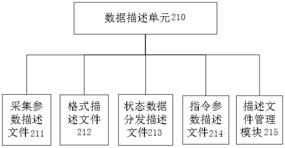
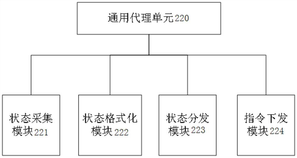
The invention provides a remote centralized monitoring system and method for a remote sensing satellite ground station network. The system comprises a subsystem-level communication component, a station-level communication component and a station network-level communication component, wherein each communication component comprises a general agent unit and a data description unit, and each communication component realizes communication connection between the corresponding communication component and corresponding to-be-acquired equipment through its general agent unit so as to realize transmission and monitoring functions of the state data of the corresponding to-be-acquired equipment; and each communication component defines the monitoring range and the monitoring content of the state dataof the to-be-acquired equipment corresponding to the communication component through the data description unit in the communication component. According to the scheme, remote centralized monitoring ofthe ground station network comprising a plurality of remote sensing satellite ground stations can be realized, and the remote centralized monitoring system uses general modular design and has a rapidexpansion capability of newly added ground station monitoring.

Description

technical field [0001] The invention relates to the technical field of remote sensing satellite reception, in particular to a remote centralized monitoring system and method for a remote sensing satellite ground station network. Background technique [0002] With the rapid development of remote sensing technology and the commercialization and industrialization of remote sensing applications in many sectors of the national economy, the number and types of remote sensing satellites have increased significantly. The station develops towards national networking and even global networking. The scale of the remote sensing satellite ground station network is becoming larger and larger, and a single remote sensing satellite ground station is composed of multiple systems, including systems composed of various professional equipment, as well as various IT systems, involving automation, communication, IT and other professional fields. The operation and maintenance personnel of each gr...

Claims


Application Information

Patent Timeline
IPC IPC(8): H04B17/40
CPCH04B17/40
Inventor 李亚林冯旭祥张洪群李安何玉王建平张雨濛牛童瑶施胜浦王阳殷慈
Owner AEROSPACE INFORMATION RES INST CAS
Learn More