Temperature measurement method and system based on automatic identification

A technology for automatic identification and detection of temperature, which is applied in temperature recording method, neural learning method, radiation pyrometry, etc. It can solve problems such as large errors in temperature measurement results, changes in temperature measurement results, and impact on detection efficiency. Achieve the effect of lifting the limitation of temperature measurement and improving the efficiency of temperature measurement

Active Publication Date: 2020-12-29
华航高科(北京)技术有限公司
View PDF5 Cites 4 Cited by
  • Summary
  • Abstract
  • Description
  • Claims
  • Application Information

AI Technical Summary

Problems solved by technology
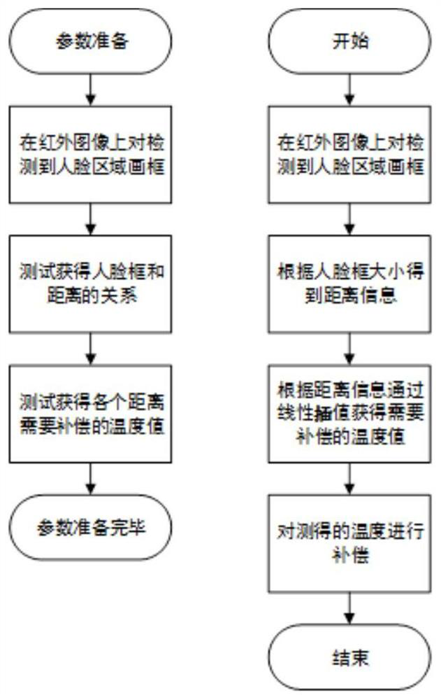
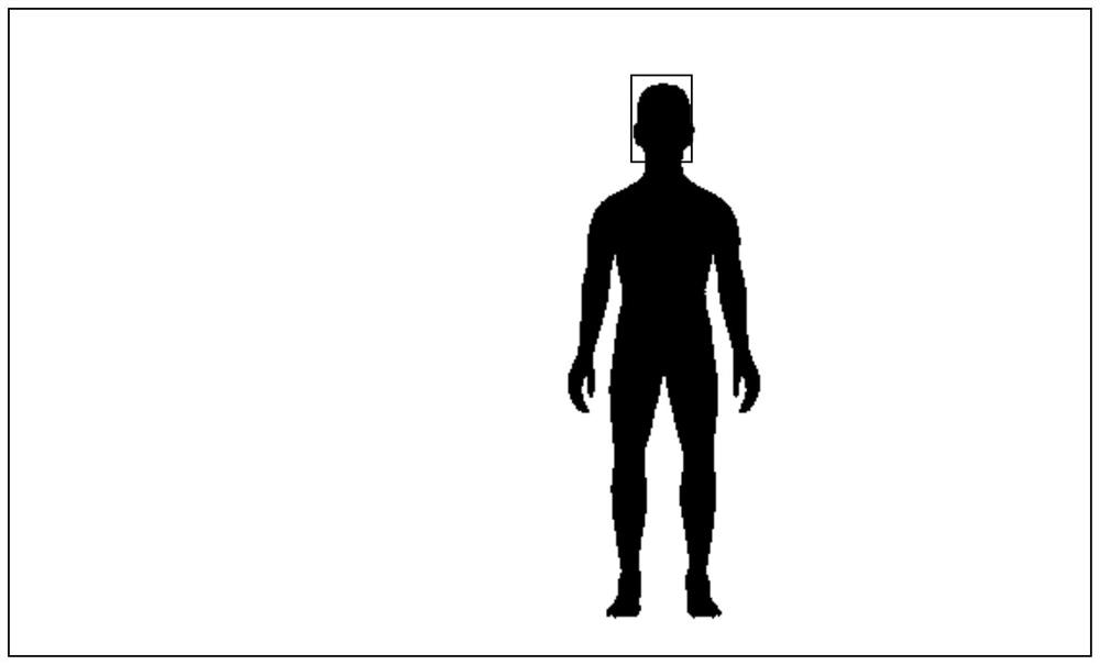
[0003] Traditional infrared detectors require the temperature measurement sample to be measured in a small specific area. If the area is not limited, when the measured sample moves, the distance between the measured sample and the temperature measurement equipment changes, and the temperature measurement The results will also change accordingly, and the temperature measurement results will have a large error
And limiting a small temperature measurement area will have a great impact on the detection efficiency
Solving the problem of the influence of distance changes on the temperature measurement results when the measured sample moves becomes the key to improving detection efficiency

Method used


Image

  • Temperature measurement method and system based on automatic identification
  • Temperature measurement method and system based on automatic identification
  • Temperature measurement method and system based on automatic identification

Examples


Embodiment Construction

[0035] The present invention will be further described in detail below in conjunction with the accompanying drawings, so that those skilled in the art can implement it with reference to the description.

[0036] It should be noted that the experimental methods described in the following embodiments are conventional methods unless otherwise specified; in the description of the present invention, the terms "transverse", "longitudinal", "upper", "lower", " The orientation or positional relationship indicated by "front", "back", "left", "right", "vertical", "horizontal", "top", "bottom", "inner" and "outer" are based on the drawings The orientation or positional relationship shown is only for the convenience of describing the present invention and simplifying the description, and does not indicate or imply that the device or element referred to must have a specific orientation, be constructed and operated in a specific orientation, and therefore cannot be construed as an important ...


PUM


Abstract

The invention discloses a temperature measurement method based on automatic identification. The method comprises the steps that an infrared image of a training sample is obtained, and the distance between the training sample and infrared imaging equipment is recorded; a designated area in each training sample infrared image is selected by using a preset shape enclosure frame, and the number of pixel points occupied by the preset shape enclosure frame is counted; the relationship between the distance and the number of the pixel points occupied by the preset shape enclosure frame is calculated;an infrared image of a to-be-detected sample is obtained, a designated area in the infrared image of the to-be-detected sample is selected by using the preset shape enclosure frame, and the number ofpixel points occupied by the preset shape enclosure frame is counted; the distance between the to-be-detected sample and the infrared imaging equipment is calculated according to the relationship between the distance and the number of the pixel points occupied by the preset shape enclosure frame; and temperature compensation is carried out on the detection temperature of the to-be-detected sampledetected through the infrared imaging equipment according to the distance between the to-be-detected sample and the infrared imaging equipment. According to the temperature measurement method, the problem that the distance changes and consequently a temperature measurement result is influenced when the to-be-measured sample moves is solved.

Description

technical field [0001] The invention relates to the field of signal control processing. More specifically, the present invention relates to a temperature measurement method and system based on automatic identification. Background technique [0002] Infrared temperature measurement is to receive the infrared radiation emitted by people or objects through the infrared detector, and convert it into an image by the signal processing system. It can convert the temperature into gray scale, and use the gray scale to reflect the temperature of people or objects. Push to get the temperature information of people or objects. [0003] Traditional infrared detectors require the temperature measurement sample to be measured in a small specific area. If the area is not limited, when the measured sample moves, the distance between the measured sample and the temperature measurement equipment changes, and the temperature measurement The result will also change accordingly, and the tempera...

Claims


Application Information

Patent Timeline
Patent Type & Authority Applications(China)
IPC IPC(8): G01J5/00G06K9/00G06N3/04G06N3/08
CPCG01J5/0025G01J5/00G06N3/08G01J2005/0077G01J5/48G06V40/161G06N3/045
Inventor 段名满
Owner 华航高科(北京)技术有限公司
Why Eureka
Try Eureka