

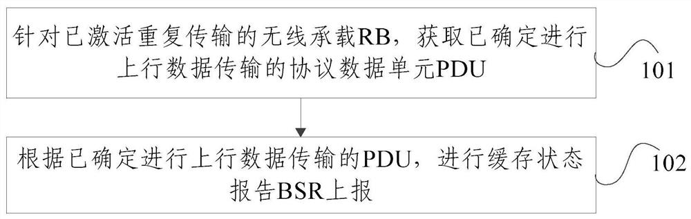
Method and device for wireless bearer buffer reporting
A technology of wireless bearer and buffer status report, applied in the field of communication, can solve the problem of base station scheduling redundant uplink resources, and achieve the effect of resource optimization and resource saving
- Summary
- Abstract
- Description
- Claims
- Application Information
AI Technical Summary
Problems solved by technology
Method used
Image

Examples
example 1
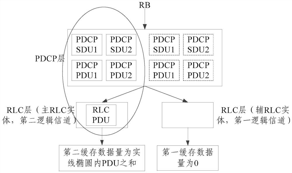
[0088] Example 1: as image 3 As shown, the RB activates repeated transmission and corresponds to two RLC entities. The RLC entity corresponding to the second logical channel is the main RLC entity and always performs data transmission of the RB. Therefore, the buffer corresponding to the logical channel group is always calculated when the data arrives. Reporting; the RLC entity corresponding to the first logical channel is a secondary RLC entity, and the first logical channel is to be used for repeated transmission. At this time, it is assumed that for the first logical channel corresponding to the PDCP entity of the RB, only the PDCP PDU and PDCP SDU are backed up at the PDCP layer (shown by the dotted box in the figure), and although the RLC entity has activated repeated transmission, the image 3 The PDCP PDU1, PDCP PDU2, PDCP SDU1, and PDCP SDU2 backed up by the PDCP layer are not repeatedly transmitted. At this time, there is no target PDCP PDU in the first logical chann...
example 2
[0090] Example 2: as Figure 4 As shown, the RB activates repeated transmission and corresponds to two RLC entities. The RLC entity corresponding to the second logical channel is the main RLC entity and always performs data transmission of the RB. Therefore, the buffer corresponding to the logical channel group is always calculated when the data arrives. Reporting; the RLC entity corresponding to the first logical channel is a secondary RLC entity, and the first logical channel is to be used for repeated transmission. At this time, it is assumed that for the first logical channel corresponding to the PDCP entity of the RB, after the PDCP layer backs up the PDCP PDU, it is handed over to the RLC layer to obtain the RLC PDU. Figure 4 The PDCP PDU1, PDCP PDU2, PDCP SDU1, PDCP SDU2 (shown by the dotted box in the figure) and the RLC PDU (shown by the dotted box in the figure) that have been delivered to the RLC layer will not be repeatedly transmitted. The target PDCP PDU and th...
example 3
[0092] Example three: as Figure 5 As shown, the RB activates repeated transmission and corresponds to two RLC entities. The RLC entity corresponding to the second logical channel is the main RLC entity and always performs data transmission of the RB. Therefore, the buffer corresponding to the logical channel group is always calculated when the data arrives. Reporting; the RLC entity corresponding to the first logical channel is a secondary RLC entity, and the first logical channel is to be used for repeated transmission. At this time, it is assumed that for the first logical channel corresponding to the PDCP entity of the RB, after the PDCP layer backs up the PDCP PDU, all the backed up PDCP PDUs are repeatedly transmitted, that is, it is determined that all the backed up PDCP PDUs are the target PDCP PDU. The first buffered data volume corresponding to the channel is the sum of the PDUs in the dotted ellipse, that is, PDCP PDU1, PDCPPDU2, PDCP SDU1, PDCP SDU2 of the PDCP lay...
PUM
 Abstract
Description
Claims
Application Information