New energy automobile charging device capable of being automatically separated
A new energy vehicle and charging device technology, applied in electric vehicle charging technology, electric vehicles, charging stations, etc., can solve problems such as inconvenience of operation and damage to auto parts, and achieve the effect of protecting vehicles, buffering collision damage and scratches
- Summary
- Abstract
- Description
- Claims
- Application Information
AI Technical Summary
Problems solved by technology
Method used
Image
Examples
Embodiment 1
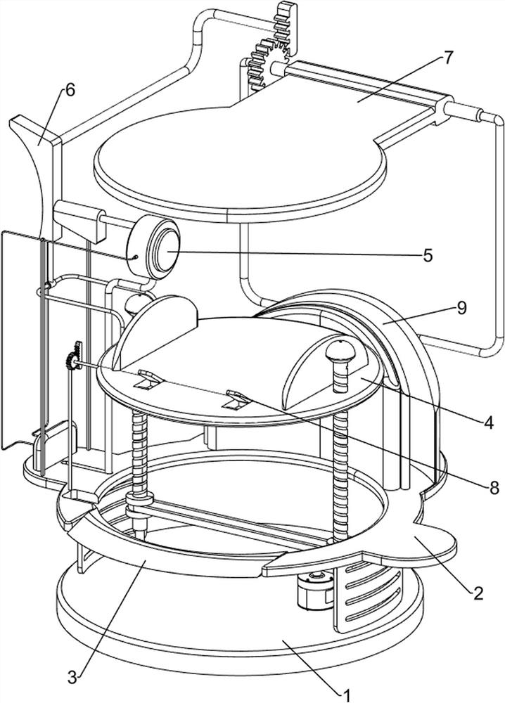
[0067] A new energy vehicle charging device that can be automatically disengaged, such as figure 1 As shown, it includes a base plate 1, a first workbench 2, an inclined ladder 3, a lifting mechanism 4 and a manual charging mechanism 5, the base plate 1 is provided with a first workbench 2, and the upper front side of the first workbench 2 is provided with an inclined ladder 3. A lifting mechanism 4 is provided in the middle of the bottom plate 1, and a manual charging mechanism 5 is provided on the left side of the top of the first workbench 2.
[0068]When people need to charge new energy vehicles, this charging device can be used. First, the driver drives the car to the lifting mechanism 4 through the inclined ladder 3 and then gets off, then starts the lifting mechanism 4, and the lifting mechanism 4 drives the car to move upward. When the car moves up to a certain position, close the lifting mechanism 4. At this time, manually push the manual charging mechanism 5 to the r...
Embodiment 2
[0070] On the basis of Example 1, such as figure 2 with image 3 As shown, the lifting mechanism 4 includes a low-speed motor 41, a screw mandrel 42, a first transmission assembly 43, a second transmission assembly 44, a second workbench 45 and a limit plate 46, and a low-speed motor 41 is installed in the middle part of the right side of the bottom plate 1. The left and right sides of the base plate 1 are provided with screw mandrels 42 for rotation, the first transmission assembly 43 is connected between the output shaft of the low-speed motor 41 and the lower part of the screw mandrel 42 on the right side, and the second transmission assembly 43 is connected between the two screw mandrels 42 bottoms. In the second transmission assembly 44 , a second workbench 45 is provided between the upper parts of the two screw rods 42 through screw connection, and the top, left and right sides of the second workbench 45 are provided with limiting plates 46 .
[0071] The driver drives...
Embodiment 3
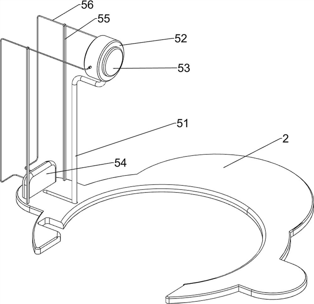
[0075] On the basis of Example 2, such as Figure 4-7 As shown, an automatic charging mechanism 6 is also included, and the left side of the top of the second workbench 45 is provided with an automatic charging mechanism 6. The automatic charging mechanism 6 is connected with the transfer box 52. Connecting ring 62, first connecting rod 63, left wedge block 64, right wedge block 65 and second connecting rod 66, the left side of the second workbench 45 top is provided with the second fixed column 61, and the left side of the second fixed column 61 is provided with There is an adapter ring 62, the adapter ring 62 is provided with a first connecting rod 63, the top of the first connecting rod 63 is provided with a left wedge block 64, the upper part of the left wall of the transfer box 52 is provided with a second connecting rod 66, and the second connecting rod 66 is arranged on the upper part of the left wall of the transfer box 52. The left end of the rod 66 is provided with a...
PUM
 Abstract
Description
Claims
Application Information
 - R&D
- Intellectual Property
- Life Sciences
- Materials
- Tech Scout
- Unparalleled Data Quality
- Higher Quality Content
- 60% Fewer Hallucinations
Browse by: Latest US Patents, China's latest patents, Technical Efficacy Thesaurus, Application Domain, Technology Topic, Popular Technical Reports.
© 2025 PatSnap. All rights reserved.Legal|Privacy policy|Modern Slavery Act Transparency Statement|Sitemap|About US| Contact US: help@patsnap.com


