
Power pole fixing and installing device for transformer

A technology of installation device and power pole, which is applied in the direction of transformer/reactor installation/support/suspension, transformer/inductor shell, etc. The effect of effective fixed support

Inactive Publication Date: 2021-01-29
张希刚
View PDF0 Cites 0 Cited by
  • Summary
  • Abstract
  • Description
  • Claims
  • Application Information

AI Technical Summary

Problems solved by technology

[0003] The existing installation of power poles for transformers is mostly done by digging deep pits on the ground to install power poles. The power poles are prone to sink after a period of time, which affects the installation and fixation of transformers.

Method used


Image

  • Power pole fixing and installing device for transformer
  • Power pole fixing and installing device for transformer
  • Power pole fixing and installing device for transformer

Examples


Embodiment 1

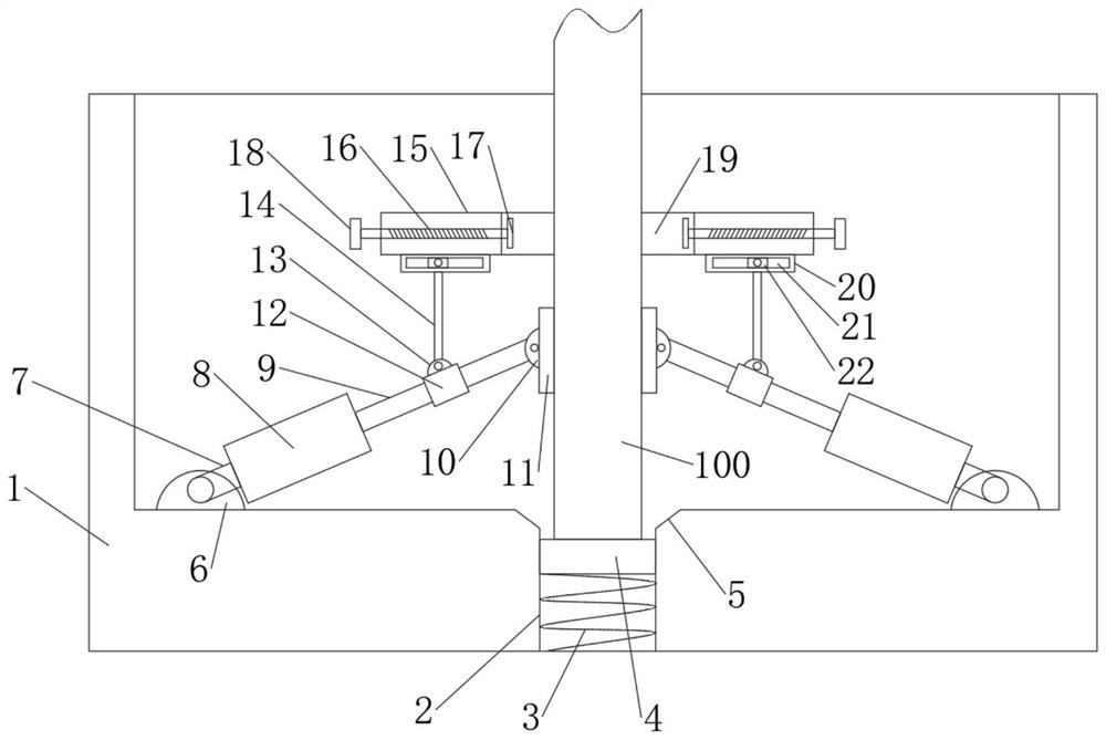
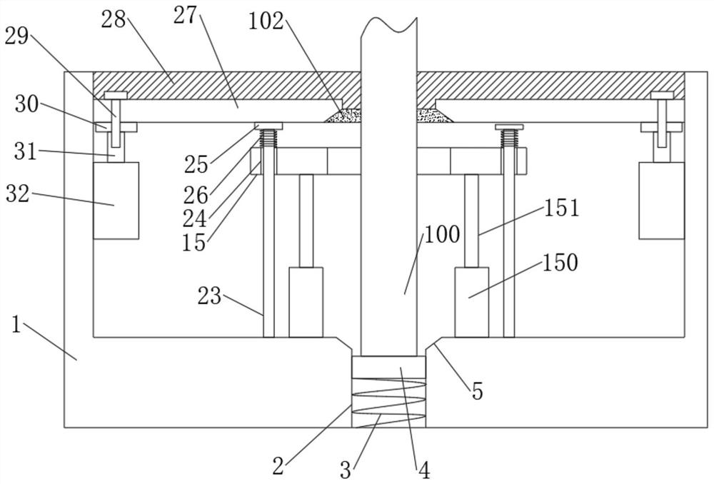
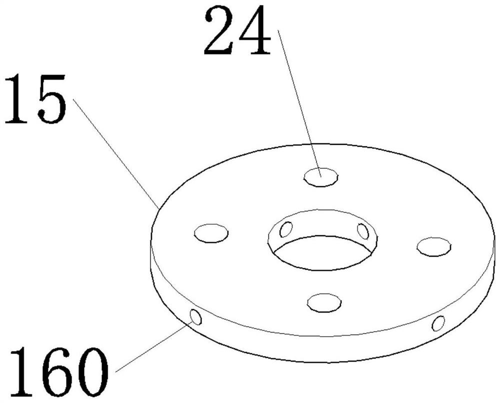
[0026] Such as Figure 1-5 As shown, a power pole fixing installation device for a transformer includes an installation frame 1, a fixing groove 2 is provided in the middle of the installation frame 1, a first spring 3 is arranged in the fixing groove 2, and a first spring 3 A bracket 4 is arranged on it, and the bracket 4 is movably installed in the fixing groove 2, and the electric pole 100 is inserted into the fixing groove 2, and the bottom of the installation frame 1 is provided with a first connecting block 6, and the The first connection block 6 is connected with the rotating rod 7, and the rotating rod 7 is fixedly connected with the first cylinder 8, and the first cylinder 8 is connected with the first telescopic column 9, and the end of the first telescopic column 9 is connected with the second telescopic column 9. The connecting blocks 10 are connected in rotation, the second connecting block 10 is provided with a first fixing plate 11, the first cylinder 8 is evenl...

Embodiment 2

[0037] This embodiment is a further improvement and limitation of embodiment 1 on the basis of embodiment 1.

[0038] A power pole fixing installation device for a transformer, including all the components in Embodiment 1, and also includes:

[0039] Further, a limiting rod 101 is arranged inside the second connecting block 10 , and a limiting groove 90 is arranged at the end of the first telescopic column 9 , and the limiting rod 101 is movably connected with the limiting groove 90 .

[0040] Specifically, the purpose of setting the limit rod 101 and the limit groove 90 is to limit the rotation angle of the first fixed plate 11, avoiding the angle of the first fixed plate 11 free rotation is too large, thereby preventing the first fixed plate 11 from It is necessary to manually adjust the angle when supporting the electric pole 100 .

[0041] The working principle of the embodiment of the present invention is:

[0042] Such as Figure 1-5 As shown, by setting the installat...


PUM


Abstract

The invention discloses a power pole fixing and mounting device for a transformer, relates to the technical field of power facility mounting, and mainly solves the problems that an existing power polefor the transformer sinks easily after being mounted, and fixation of the transformer is affected. The device comprises a mounting frame, a fixing groove is formed in the middle of the mounting frame, a first spring is arranged in the fixing groove, a bracket is arranged on the first spring, the bracket is movably mounted in the fixing groove, an electric pole is inserted into the fixing groove,and a first connecting block is arranged at the bottom of the mounting frame; the first connecting block is connected with a rotating rod, the rotating rod is fixedly connected with a first air cylinder, the first air cylinders are connected with first telescopic columns, the tail ends of the first telescopic columns are rotationally connected with second connecting blocks, a first fixing plate isarranged on the second connecting blocks, and the first air cylinders are evenly arranged in the circumferential direction of the electric pole. And a sliding sleeve is mounted on each first telescopic column in a sliding manner.

Description

technical field [0001] The invention relates to the technical field of electric facility installation, in particular to a power pole fixing installation device for a transformer. Background technique [0002] Power poles are devices used to erect power facilities or wires. In rural areas, unlike urban areas, real-time monitoring is not possible, and fences are set up to isolate transformers. The rural environment is complex, and livestock, poultry, and wild animals have a wide range of activities. For transformers It has a certain influence, and it is easy to touch the transformer, and the protective effect of building a fence is also small. Therefore, the installation of transformers in rural areas is mainly carried out by lifting and erecting power poles, so as to ensure that the transformer is at a higher position and ensure the safety of the transformer. safety. [0003] The existing installation of power poles for transformers is mostly done by digging deep pits on the...

Claims


Application Information

Patent Timeline
Patent Type & Authority Applications(China)
IPC IPC(8): H01F27/06H01F27/02
CPCH01F27/02H01F27/06
Inventor 张希刚
Owner 张希刚
Learn More