Ventilation device based on building design
A ventilation device and architectural design technology, applied in ventilation systems, space heating and ventilation, space heating and ventilation details, etc., can solve problems affecting the health of users, dust accumulation, and hand collection devices without cleaning devices, etc. Achieve the effect of comprehensive dust scraping, easy cleaning and operation, and good sealing effect
- Summary
- Abstract
- Description
- Claims
- Application Information
AI Technical Summary
Problems solved by technology
Method used
Image
Examples
Embodiment 1
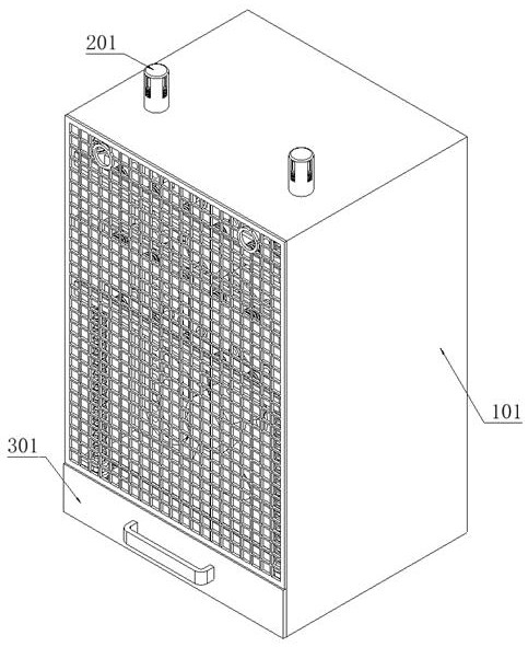
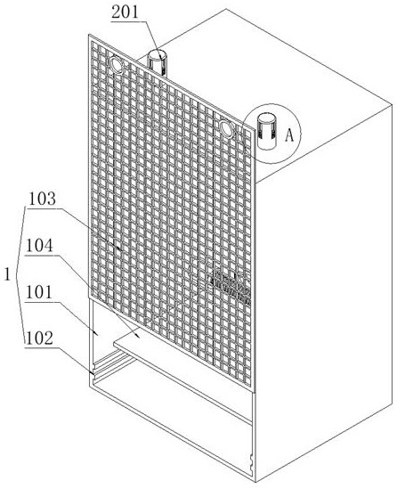
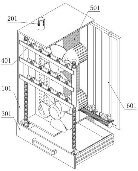
[0088] as attached figure 1 to attach Figure 11 Shown:
[0089] The present invention provides a ventilation device based on architectural design, including a supporting frame device 1;
[0090] A supporting frame device 1, the supporting frame device 1 is a hollow box structure, and the supporting frame device 1 is fixedly connected to the ventilation device 5;
[0091] Two wall fixing devices 2 are provided, and the two wall fixing devices 2 slide respectively on both sides of the top of the supporting frame device 1;
[0092] The collecting device 3 is slidably connected to the bottom of the supporting frame device 1;
[0093] A cleaning device 4, the cleaning device 4 is fixedly connected to the supporting frame device 1, and both sides of the cleaning device 4 are engaged with the collecting device 3;
[0094] The air intake device 6 is fixedly connected to the back of the support frame device 1 .
[0095] Wherein, the support frame device 1 comprises:
[0096] Sup...
Embodiment 2
[0136] Such as Figure 12 As shown, in this embodiment, other structures remain unchanged. On the basis of Embodiment 1, this embodiment provides another installation method of the dust-proof net frame 103, and a sliding groove is provided on both sides of the front side of the supporting shell 101. , and the sliding groove is slidably connected with a dustproof net frame 103 (see Figure 12 ), instead of the fixed connection between the dust-proof net frame 103 and the support shell 101, the sliding connection is used to install more quickly, and at the same time, it is convenient to check and repair the inside of the equipment, and at the same time, it is more convenient to disassemble and replace, which greatly improves the practical value.
Embodiment 3
[0138] Such as Figure 13 As shown, in this embodiment, on the basis of Embodiment 1, other structures remain unchanged. This embodiment provides another push-pull collection box 301 structural form, and a stainless steel shrapnel is fixedly connected to both sides of the push-pull collection box 301. At the same time, a slot is provided on both sides of the bottom of the support shell 101, which cooperates with the stainless steel shrapnel to realize that the push-pull collection box 301 can be limited and fixed by the stainless steel shrapnel after the push-pull collection box 301 is pushed, so that the daily use of the equipment is more stable and prevents accidentally slipped out.
[0139] When in use: First, remove the two wall fixing devices 2 of the equipment, then place the supporting frame device 1 in the pre-set opening of the building wall, and then insert the two wall fixing devices 2 Installed on the top of the supporting shell 101, then the expansion claw 205 ca...
PUM
 Abstract
Description
Claims
Application Information
 - R&D
- Intellectual Property
- Life Sciences
- Materials
- Tech Scout
- Unparalleled Data Quality
- Higher Quality Content
- 60% Fewer Hallucinations
Browse by: Latest US Patents, China's latest patents, Technical Efficacy Thesaurus, Application Domain, Technology Topic, Popular Technical Reports.
© 2025 PatSnap. All rights reserved.Legal|Privacy policy|Modern Slavery Act Transparency Statement|Sitemap|About US| Contact US: help@patsnap.com


