Anti-falling hydraulic lifting mechanism and equipment

A hydraulic lifting and anti-falling technology, applied in the direction of lifting frame, lifting device, etc., can solve the problems of poor safety, inability to perform secondary protection during the landing process, and inability to perform anti-falling protection, etc.

Inactive Publication Date: 2021-02-02
苏州威尔力液压升降机械有限公司
View PDF6 Cites 0 Cited by
  • Summary
  • Abstract
  • Description
  • Claims
  • Application Information

AI Technical Summary

Problems solved by technology

[0005] The purpose of the present invention is to provide an anti-falling hydraulic lifting mechanism and equipment to solve the problems in the prior art that the lifting control is not stable enough, the safety is poor, and the anti-falling protection cannot be performed, and the landing process of the lifting platform cannot be automatically balanced. , the problem that secondary protection cannot be performed during the landing process

Method used


Image

  • Anti-falling hydraulic lifting mechanism and equipment
  • Anti-falling hydraulic lifting mechanism and equipment
  • Anti-falling hydraulic lifting mechanism and equipment

Examples


Embodiment 1

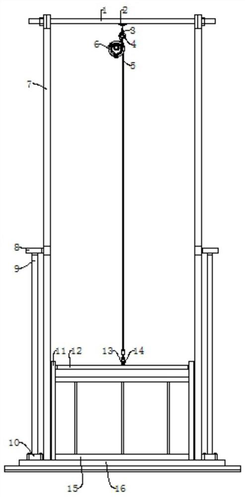
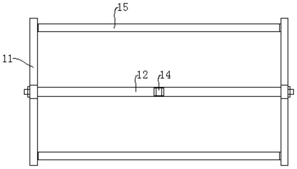
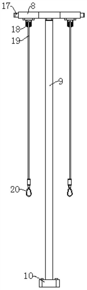
[0020] see Figure 1~3 , in the embodiment of the present invention, a kind of anti-falling hydraulic lifting mechanism and equipment, comprises lift frame 7, and hanger bar 1 is installed on the top between lift frame 7, and hanger bar 1 is convenient to install and fix with the first connecting plate 2, and hanger bar The middle part of the bottom end of 1 is equipped with a first connecting plate 2, and the bottom of the first connecting plate 2 is equipped with a first suspension ring 3, which is convenient for the installation of the self-locking spring balancer 6, and a self-locking spring balancer 6 is installed on the first suspension ring 3. The spring balancer 6, the self-locking spring balancer 6 is used to carry out self-locking balance control to the lifting platform 15, the outside of the self-locking spring balancer 6 is equipped with a hook 4, the hook 4 is suspended and connected with the first suspension ring 3, and the self-locking spring balance The inside ...

Embodiment 2

[0023] see Figure 1~3 , in the embodiment of the present invention, a kind of anti-falling hydraulic lifting mechanism and equipment, comprises lift frame 7, and hanger bar 1 is installed on the top between lift frame 7, and hanger bar 1 is convenient to install and fix with the first connecting plate 2, and hanger bar The middle part of the bottom end of 1 is equipped with a first connecting plate 2, and the bottom of the first connecting plate 2 is equipped with a first suspension ring 3, which is convenient for the installation of the self-locking spring balancer 6, and a self-locking spring balancer 6 is installed on the first suspension ring 3. The spring balancer 6, the self-locking spring balancer 6 is used to carry out self-locking balance control to the lifting platform 15, the outside of the self-locking spring balancer 6 is equipped with a hook 4, the hook 4 is suspended and connected with the first suspension ring 3, and the self-locking spring balance The inside ...


PUM


Abstract

The invention discloses an anti-falling hydraulic lifting mechanism and equipment. Lifting frames are included, a lifting rod is installed at the top between the lifting frames, a first connecting plate is installed in the middle of the bottom end of the lifting rod, a first lifting ring is installed at the bottom of the first connecting plate, and a self-locking spring balancer is installed on the first lifting ring; and a stable base is installed at the bottom ends of the lifting frames, and a lifting table is installed in the middle of the top end of the stable base. Side protection platesare installed on the two sides of the lifting table and slidably connected with the lifting frames, so that lifting of the lifting frames is stable, second connecting plates are installed at one endsof hydraulic rods, traction ropes are installed on the two sides of the bottoms of the second connecting plates through hanging wheels, and one ends of the traction ropes are connected with the two sides of the tops of the side protection plates through third hanging rings; and stable lifting control is achieved, the self-locking spring balancer is installed in the middle of the bottom end of thelifting rod, and an anti-falling rope is installed in the self-locking spring balancer.

Description

technical field [0001] The invention relates to the field of hydraulic lifting mechanism and equipment, in particular to an anti-falling hydraulic lifting mechanism and equipment. Background technique [0002] The hydraulic lifting mechanism and equipment is a lifting device controlled by hydraulic lifting. The hydraulic lifting platform is a multi-functional lifting and loading mechanical equipment. The hydraulic lifting platform is divided into four-wheel mobile lifting platform, two-wheel traction lifting platform, Car modified lifting platform, hand-push lifting platform, hand-cranked lifting platform, AC and DC dual-purpose lifting platform, battery vehicle-mounted lifting platform, hydraulic lifting platform can be customized according to user requirements. [0003] Used in high-altitude operations and maintenance in factories, automatic warehouses, parking lots, municipal administration, docks, construction, decoration, logistics, electricity, transportation, petroleu...

Claims


Application Information

Patent Timeline
Patent Type & Authority Applications(China)
IPC IPC(8): B66F7/02B66F7/04B66F7/28
CPCB66F7/02B66F7/04B66F7/28
Inventor 吴卫平
Owner 苏州威尔力液压升降机械有限公司
Why Eureka
Try Eureka