Refrigerator
A technology for refrigerators and cabinets, applied in the field of refrigerators, which can solve problems such as unbalanced lifting, reduction of the internal volume of the cabinet, safety issues, etc., and achieve the goals of improving the convenience of use, minimizing the loss of storage space, and minimizing the storage space loss effect
- Summary
- Abstract
- Description
- Claims
- Application Information
AI Technical Summary
Problems solved by technology
Method used
Image

Examples
Embodiment Construction
[0132] Next, specific embodiments of the present invention will be described in detail with reference to the accompanying drawings. However, the technical idea of the present invention is not limited to the disclosed embodiments, and other retrogressive inventions or other embodiments within the scope of the idea of the present invention can be easily obtained through addition, modification, deletion, etc. of other constituent elements.
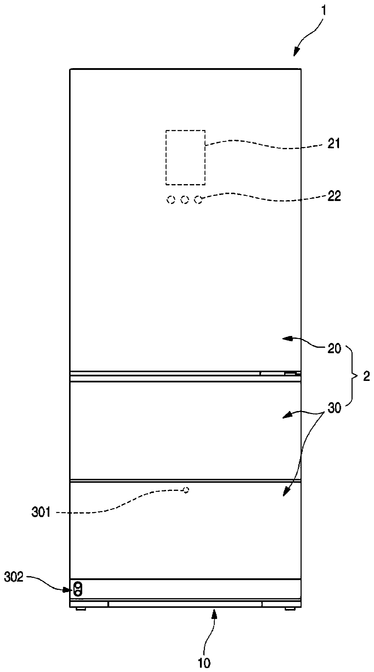
[0133] figure 1 is a front view of the refrigerator of the first embodiment of the present invention.
[0134] As shown in the figure, the outer shape of the refrigerator 1 may be formed by a box body 10 forming a storage space and a door 2 for covering a front side of an opening of the box body 10 .
[0135] The storage space inside the box body 10 can be divided into multiple spaces. For example, the upper space of the box body 10 can be divided into a refrigerator compartment, and the lower space can be divided into a freezer compart...
PUM
 Abstract
Description
Claims
Application Information
 - R&D
- Intellectual Property
- Life Sciences
- Materials
- Tech Scout
- Unparalleled Data Quality
- Higher Quality Content
- 60% Fewer Hallucinations
Browse by: Latest US Patents, China's latest patents, Technical Efficacy Thesaurus, Application Domain, Technology Topic, Popular Technical Reports.
© 2025 PatSnap. All rights reserved.Legal|Privacy policy|Modern Slavery Act Transparency Statement|Sitemap|About US| Contact US: help@patsnap.com