Punching positioning device for automobile frame

A technology of positioning device and automobile frame, which is applied to vehicle parts, transportation and packaging, etc., can solve the problems of slow speed and low drilling efficiency, and achieve the effect of fast drilling

Active Publication Date: 2021-02-05
SHANDONG JIAOTONG UNIV
View PDF9 Cites 1 Cited by
  • Summary
  • Abstract
  • Description
  • Claims
  • Application Information

AI Technical Summary

Problems solved by technology

[0003] When punching thin parts, the punching speed is fast, so in order to improve production efficiency, the speed of moving the workpiece position needs to be accelerated. The traditional cylinder and lead screw change the punching position at a slow speed, especially when processing into batches. For thin parts, frequent replacement of workpieces for drilling is very inefficient

Method used


Image

  • Punching positioning device for automobile frame
  • Punching positioning device for automobile frame
  • Punching positioning device for automobile frame

Examples


Embodiment 1

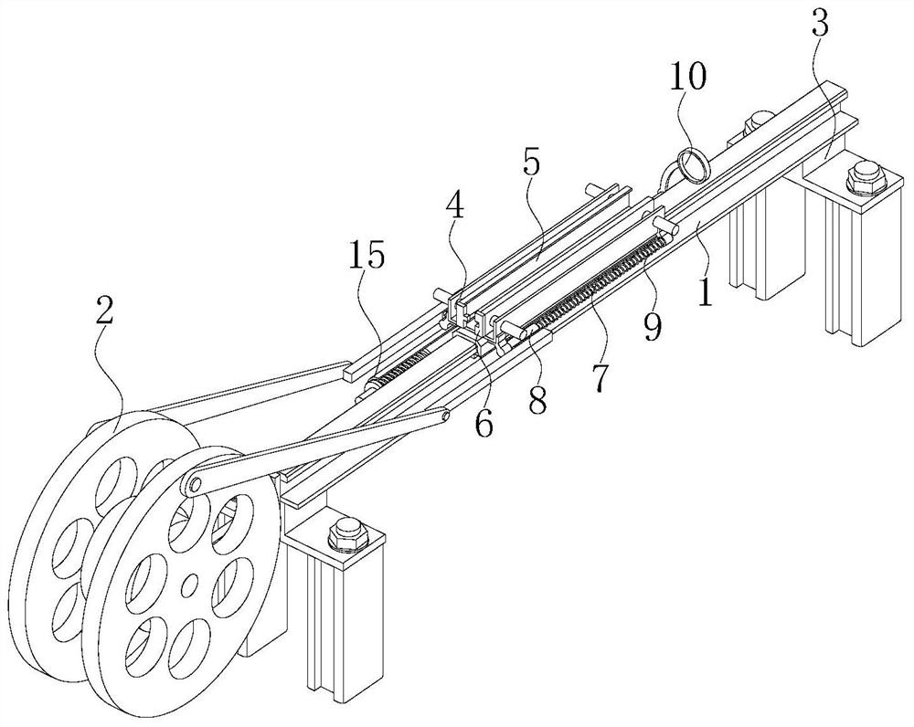
[0028] Such as Figure 1-7 As shown, a punching and positioning device for an automobile frame includes a guide rail 1, a reciprocating mechanism 2 and two brackets 3, the reciprocating mechanism 2 is installed on the left end of the guide rail 1, and the two brackets 3 are respectively located at the left and right sides of the guide rail 1. On the side, the two brackets 3 are fixedly connected with the guide rail 1, the bracket 3 can be used to support the guide rail 1, the bracket 3 can be connected with other devices, a U-shaped plate 4 is arranged above the guide rail 1, and the U-shaped plate 4 slides with the guide rail 1 connection, the bottom surface of the U-shaped plate 4 is fixed with a sliding sleeve 14, the sliding sleeve 14 is clamped on the upper end of the guide rail 1, the sliding sleeve 14 is slidingly connected with the guide rail 1, and two splints 5 are installed inside the U-shaped plate 4, U-shaped A hydraulic cylinder is installed on the plate 4, which...

Embodiment 2

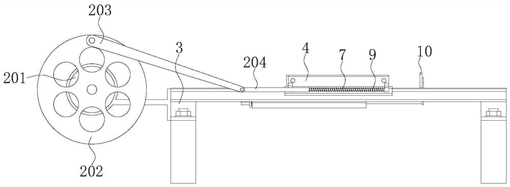
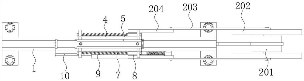
[0032] Such as Figure 1-4 As shown, the reciprocating mechanism 2 includes a biaxial motor 201, two flywheels 202 and two rockers 203, the biaxial motor 201 is fixedly connected with the left end of the guide rail 1, and the two flywheels 202 are respectively connected to the two outputs of the biaxial motor 201. The shafts are fixedly connected, and one end of the two rockers 203 is rotationally connected to the sides of the two flywheels 202 away from each other. The rotational connection between the rocker 203 and the flywheel 202 is located at the eccentric position of the flywheel 202, and the two rockers 203 are far away from the two flywheels. One end of the 202 is hinged with a cross bar 204 , and the ends of the two cross bars 204 away from the two rockers 203 are respectively fixedly connected with the two sliders 8 .

[0033] When in use, the thin parts that make up the automobile body frame can be placed between the two splints 5 through the grabbing mechanism, an...


PUM


Abstract

The invention provides a punching positioning device for an automobile frame, and relates to the technical field of automobile frame punching. The punching positioning device for the automobile framecomprises a guide rail, a reciprocating mechanism and two supports, the reciprocating mechanism is arranged at the left end of the guide rail, the two supports are located on the left side and the right side of the lower portion of the guide rail separately and are fixedly connected to the guide rail, a U-shaped plate is arranged above the guide rail and is connected to the guide rail in a slidingmode, two clamping plates are arranged in the U-shaped plate, and limiting plates A are fixedly arranged at the left ends of the two clamping plates. According to the punching positioning device forthe automobile frame, by arranging the clamping plates, a sliding block, a spring A, the reciprocating mechanism, a control mechanism and a spring B, the rapid punching effect is achieved, and the problems that in the prior art, a mode of changing the punching position by adopting an air cylinder and a lead screw is low in speed, and especially when batched thin parts are machined, the punching efficiency is very low due to frequent replacement of workpieces can be solved.

Description

technical field [0001] The invention relates to the technical field of automobile frame punching, in particular to an automobile frame punching positioning device. Background technique [0002] The automobile frame is bulky and complex in structure. In addition to beams and longitudinal beams, there are many small parts welded together with the main body of the frame. Most of these small parts need to be punched. The punching process of the automobile frame is generally to manufacture the main body of the frame first, and prepare the blank of the punching part, and punch the blank of the punching part to make it a punching machine. Finished hole parts; then weld the finished punched parts with the main body of the frame to form a finished frame with holes. The defect of this production process is that the size accuracy and shape accuracy of the mounting holes on the parts on the automobile frame are low, which seriously affects the handling stability and safety of the autom...

Claims


Application Information

Patent Timeline
Patent Type & Authority Applications(China)
IPC IPC(8): B21D28/04B21D28/24B21D53/88
CPCB21D28/04B21D28/24B21D53/88
Inventor 刘新磊周长峰王希波衣丰艳
Owner SHANDONG JIAOTONG UNIV
Why Eureka
Try Eureka