Anti-falling type rim mounting structure

A technology for installing structures and rims, applied in the directions of rims, transportation and packaging, vehicle parts, etc., can solve the problems of the lock ring not being locked in place, the lock ring coming off the slot, affecting the inflation effect, etc. Potential safety hazards and the effect of saving labor costs

Pending Publication Date: 2021-02-05
ZHENJIANG CORIM MFR
View PDF0 Cites 0 Cited by
  • Summary
  • Abstract
  • Description
  • Claims
  • Application Information

AI Technical Summary

Problems solved by technology

[0002] As we all know, automobile tires must be installed through the rim, especially for large vehicles, the importance of the rim in the vehicle is even more prominent. A set of locking parts for locking. The existing rim locking parts generally include an integrally formed inclined surface on one side of the rim edge that cooperates with the rim as a set of fixed locking parts and is set on the other side of the rim edge. The detachable seat ring and lock ring cooperate with the wheel rim as another set of detachable locking parts. In the existing structure, during the inflation process, as the gas volume increases, the seat ring will move and press on the seal. On the ring and cooperate with the lock ring to achieve the purpose of not leaking air. However, in the actual application process, there will often be a problem that the lock ring is not locked in place. At this time, there are usually two situations during the inflation process. One is that during the inflation process, when the lock ring is not locked in place at all, the lock ring will be easily released from the slot after inflation. At this time, the seat ring cannot be pressed against the sealing ring, and the gas cannot be filled, which affects the inflation effect. The second is when the lock ring is not completely in place, that is, when the lock ring is in a stagnant state, and then inflated at this time, when the gas reaches a certain amount, the lock ring will suddenly be disengaged, which has caused serious safety hazards.

Method used


Image

  • Anti-falling type rim mounting structure

Examples


Embodiment 1

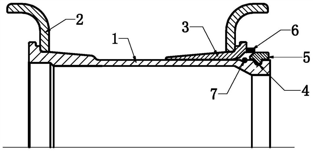
[0020] Such as figure 1 As shown, the anti-off rim installation structure of this embodiment includes a rim 1, a left rim that can be placed on the left end of the rim, and a right rim that can be placed on the right end of the rim. Between the seat ring 3, the root of the seat ring 3 is provided with a flat section that matches the rim 2, thus greatly improving the fit of the fit and installation, and the end of the seat ring 3 is used to block the right rim to make it The flanging structure that will not fall off, the seat ring 3 has an outer surface that extends obliquely upward from the inside of the rim to the outside of the rim, the center of the rim is defined as the inside of the rim, that is, the part between the two rims is defined as the inside of the rim, and the outside of the rim The part defined as the outer side of the rim, the left edge of the rim 1 is directly set as an outer surface that extends upwardly from the inside of the rim to the outside of the rim, ...

Embodiment 2

[0023] The anti-off rim installation structure of this embodiment includes a rim 1, a left rim that can be placed on the left end of the rim, and a right rim that can be placed on the right end of the rim. The left seat ring, the left edge of the rim 1 is provided with a left seat ring (not shown in the figure) between the rim and the left wheel rim, and the roots of the left seat ring and the right seat ring are provided with a section that is connected with the left wheel rim and the right wheel rim. The plane section that fits the rim, thus greatly improving the fit of the installation. The end of the seat ring 3 has a flanging structure for blocking the right wheel rim so that it will not fall off. Both the left seat ring and the right seat ring have from The inner surface of the rim is inclined upwards to the outer surface of the rim, and the central position of the rim is defined as the inner rim, that is, the part between the two rims is defined as the inner side of the ...


PUM


Abstract

The invention discloses an anti-falling type rim mounting structure. The anti-falling type rim mounting structure comprises a rim and two wheel flanges, wherein the two wheel flanges can be arranged at the left end and the right end of the wheel rim in a sleeving mode, at least one side edge of the wheel rim is provided with a seat ring located between the wheel rim and the wheel flanges, the wheel rim is provided with a clamping groove located in the outer side of the seat ring, a locking ring is arranged in the clamping groove, and the seat ring is provided with a limiting piece capable of limiting the locking ring. And the locking ring can be accurately clamped in the clamping groove through the limiting piece. The inflation device has the advantages that inflation can be performed onlyafter the locking ring is accurately limited in the clamping groove, it is guaranteed that the locking ring cannot be disengaged during inflation, inflation cannot be performed when the locking ringis not in the clamping groove, the inflation effect is good, potential safety hazards are avoided, the structure is simple, manufacturing is easy, installation is rapid and convenient, use reliabilityis very good, labor cost is saved, and production cost is reduced.

Description

technical field [0001] The invention relates to a mounting structure for wheel rim parts, in particular to an anti-off type wheel rim mounting structure. Background technique [0002] As we all know, automobile tires must be installed through the rim, especially for large vehicles, the importance of the rim in the vehicle is even more prominent. A set of locking parts for locking. The existing rim locking parts generally include an integrally formed inclined surface on one side of the rim edge that cooperates with the rim as a set of fixed locking parts and is set on the other side of the rim edge. The detachable seat ring and lock ring cooperate with the wheel rim as another set of detachable locking parts. In the existing structure, during the inflation process, as the gas volume increases, the seat ring will move and press on the seal. On the ring and cooperate with the lock ring to achieve the purpose of not leaking air. However, in the actual application process, there...

Claims


Application Information

Patent Timeline
Patent Type & Authority Applications(China)
IPC IPC(8): B60B21/10
CPCB60B21/102B60B21/104B60B21/108
Inventor 王闯史跃明
Owner ZHENJIANG CORIM MFR
Why Eureka
Try Eureka