Intelligent spraying equipment
A spraying equipment and intelligent technology, applied in the field of intelligent spraying equipment, can solve problems such as low efficiency
- Summary
- Abstract
- Description
- Claims
- Application Information
AI Technical Summary
Problems solved by technology
Method used
Image
Examples
specific Embodiment approach 1
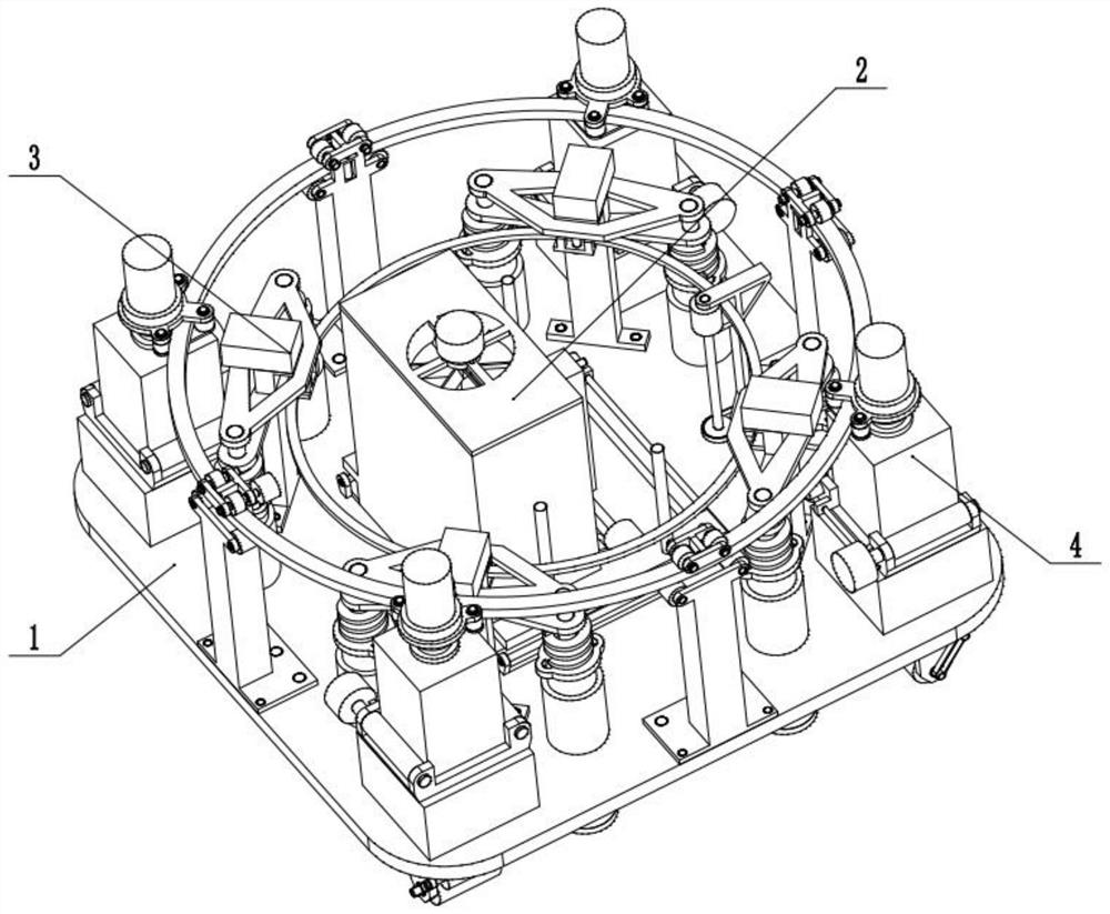
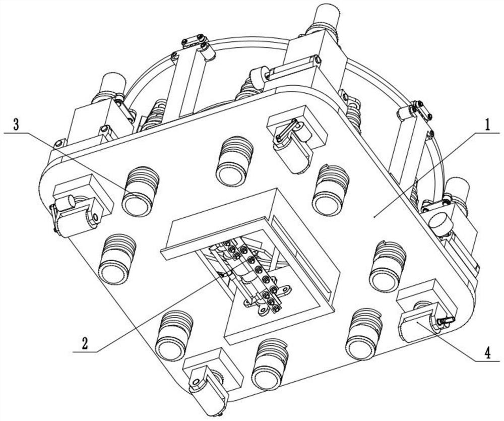
[0034] Combine below figure 1 , figure 2 , image 3 , Figure 4 , Figure 5 , Figure 6 , Figure 7 , Figure 8 , Figure 9 , Figure 10 , Figure 11 , Figure 12 , Figure 13 , Figure 14 , Figure 15 , Figure 16 Describe this embodiment. The present invention relates to a spraying equipment device, more specifically, an intelligent spraying equipment, including a base 1, a spraying mechanism 2, a sensing mechanism 3, and a pushing mechanism 4. The device can be adjusted by an induction feedback device. Level height, and to adapt to different terrains, the device can blow away the road dust through the fan, and the device can adjust the spraying width.
[0035] The spraying mechanism 2 is slidingly matched with the base 1, the sensing mechanism 3 is fixed on the upper part of the base 1, and the pushing mechanism 4 is connected with the base 1 below.
specific Embodiment approach 2
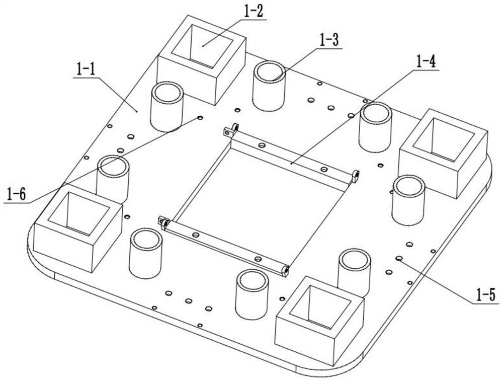
[0037] Combine below figure 1 , figure 2 , image 3 , Figure 4 , Figure 5 , Figure 6 , Figure 7 , Figure 8 , Figure 9 , Figure 10 , Figure 11 , Figure 12 , Figure 13 , Figure 14 , Figure 15 , Figure 16 Describe this embodiment, this embodiment will further explain the first embodiment, the base 1 includes a bottom plate 1-1, a pushing groove 1-2, an induction groove 1-3, a spraying chute 1-4, a fixing hole 1- 5. Fixing hole 2 1-6, the bottom plate 1-1 is square, the middle of the bottom plate 1-1 is processed with a square hole, and there are four pushing grooves 1-2, and the pushing grooves 1-2 are located at the four corners of the base plate 1-1 , there are eight induction slots 1-3, the induction slots 1-3 are evenly distributed on the upper part of the base 1-1, the spraying chute 1-4 is located in the middle of the base plate 1-1, and the spraying chute 1-4 is processed Sliding holes are arranged, four groups of fixed holes 1-5 are provided, ...
specific Embodiment approach 3
[0039] Combine below figure 1 , figure 2 , image 3 , Figure 4 , Figure 5 , Figure 6 , Figure 7 , Figure 8 , Figure 9 , Figure 10 , Figure 11 , Figure 12 , Figure 13 , Figure 14 , Figure 15 , Figure 16 Describe this embodiment, this embodiment will further explain the first embodiment, the spraying mechanism 2 includes a box 2-1, an upper cover 2-2, a fan 2-3, a lifting screw 2-4, an intermediate connecting rod 2 -5, screw motor 2-6, intermediate connecting rod 2-7, width motor 2-8, belt 2-9, adjusting stud 2-10, nozzle box 2-11, connecting frame 2-12, fixed nozzle box 2-13, nozzle 2-14, connecting pipe 2-15, square through holes are processed on the lower part of one side of the box body 2-1, plate-shaped support frames are processed on both sides of the box body 2-1, and the upper cover 2-2 is fixed on The upper part of the box body 2-1 is processed with through holes on the upper cover 2-2, the upper part of the fan 2-3 is the motor and the lowe...
PUM
 Abstract
Description
Claims
Application Information
 - R&D
- Intellectual Property
- Life Sciences
- Materials
- Tech Scout
- Unparalleled Data Quality
- Higher Quality Content
- 60% Fewer Hallucinations
Browse by: Latest US Patents, China's latest patents, Technical Efficacy Thesaurus, Application Domain, Technology Topic, Popular Technical Reports.
© 2025 PatSnap. All rights reserved.Legal|Privacy policy|Modern Slavery Act Transparency Statement|Sitemap|About US| Contact US: help@patsnap.com


