
An intelligent unmanned ship path planning method based on improved artificial potential field

A path planning and artificial potential field technology, applied in two-dimensional position/channel control, vehicle position/route/height control, instruments, etc., can solve target unreachable, energy consumption loss, unmanned ships and obstacles increased risk of collision

Active Publication Date: 2022-05-10
浙大宁波理工学院
View PDF1 Cites 0 Cited by
  • Summary
  • Abstract
  • Description
  • Claims
  • Application Information

AI Technical Summary

Problems solved by technology

When the initial position of the unmanned ship is far away from the target point, the unmanned ship will be subjected to a particularly large gravitational force, so that the repulsion potential field generated by the nearby obstacles is almost negligible, then the unmanned ship collides with the obstacle at this time the risk of
[0006] (2) Target unreachable problem
If the moving direction of the dynamic obstacle deviates from or deviates from the unmanned ship, or the relative distance between the stop position of the obstacle and the unmanned ship does not threaten the safety of the unmanned ship, then in this case the unmanned ship is repelled The local arc obstacle avoidance path calculated and planned by the potential field is not only invalid, but will bring some unnecessary energy loss
[0008] (4) Local minimum problem
However, when the unmanned ship is in a straight line with the obstacle and the target position, under the joint action of the gravitational potential field and the repulsive potential field, the unmanned ship may be in a state of force balance, then the unmanned ship will In the case of not reaching the target point, stop or partially reciprocate

Method used

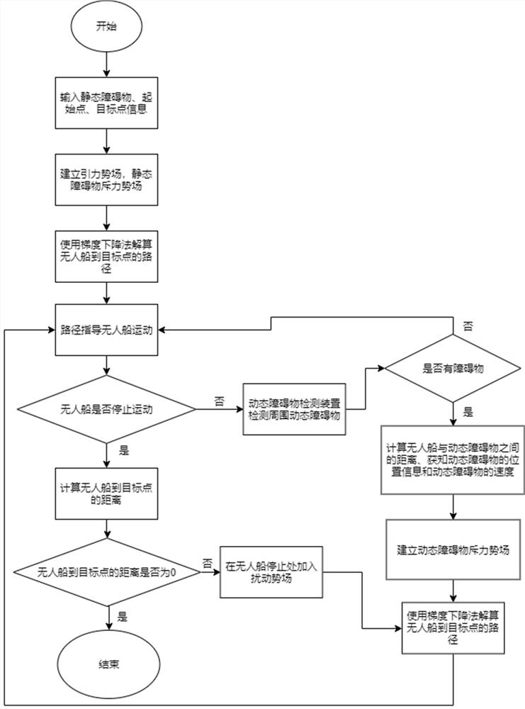
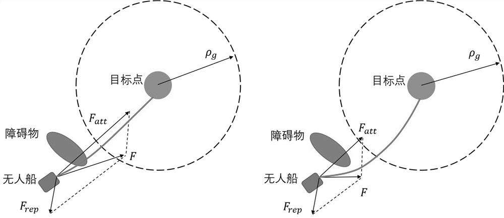

Image

  • An intelligent unmanned ship path planning method based on improved artificial potential field
  • An intelligent unmanned ship path planning method based on improved artificial potential field
  • An intelligent unmanned ship path planning method based on improved artificial potential field

Examples


Embodiment approach

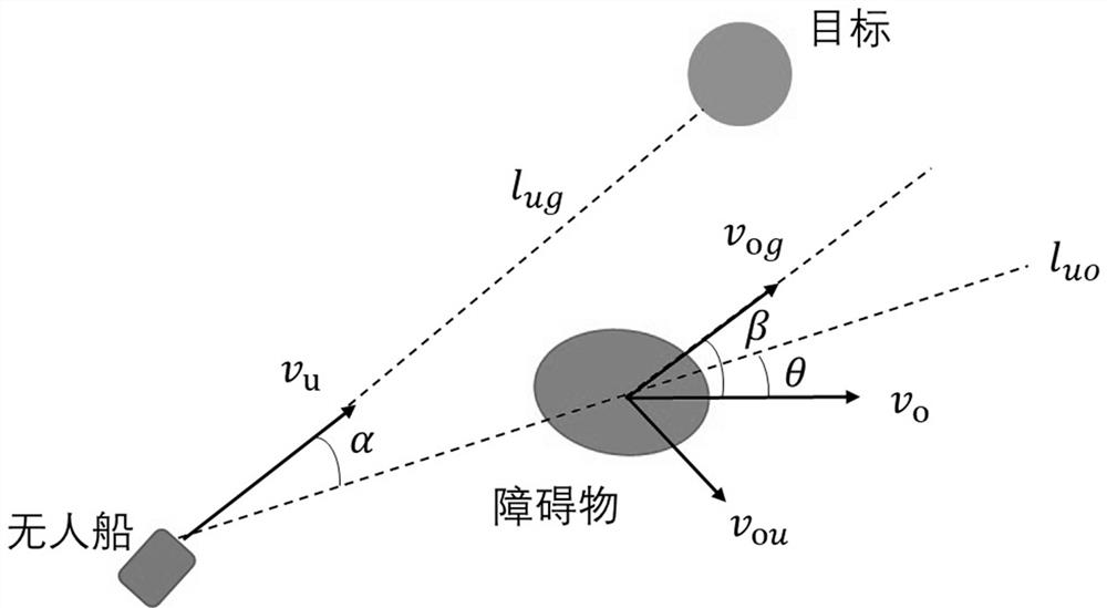
[0080] In the above embodiment, in addition to eliminating the interference that the dynamic obstacle is not in the threat area, the influence of the relative position and relative running speed between the dynamic obstacle and the unmanned ship on the obstacle avoidance path planning of the unmanned ship should also be considered. v u and v o are the moving speeds of the unmanned ship and the obstacle, respectively; l ug is the straight-line path from the unmanned ship to the target, and the direction is the same as v u the same; l uo is the straight path from the unmanned ship to the obstacle, and the direction is from the unmanned ship to the obstacle; v ou and v og are respectively the moving speed v of the obstacle o Components, where v ou means v o in vertical l ug Component in direction, v og means v o in v u Components in the direction; α, β, θ represent v respectively u Direction and unmanned ship and obstacle connection l uo angle, v og direction and v ...


PUM


Abstract

The invention relates to an unmanned ship path planning method, in particular an intelligent unmanned ship path planning method based on an improved artificial potential field. It is based on an improved potential field constructor and uses a gradient descent method to calculate the unmanned ship's path from the current The path from the position to the target point, thereby guiding the movement of the unmanned ship; in view of the local minimum problem existing in the process of automatic obstacle avoidance of the unmanned ship, the concept of disturbance potential energy is introduced to break the local force balance of the unmanned ship. status, thus promoting the automatic obstacle avoidance navigation of unmanned ships. This invention effectively solves the four shortcomings of the traditional artificial potential field algorithm in the field of automatic driving and obstacle avoidance of unmanned ships, namely, the problem that the unmanned ship may collide with obstacles when it is far away from the target and close to the obstacle, and the target cannot be reached. reach problems, energy consumption problems caused by ineffective obstacle avoidance planning, and local minimum problems. The present invention considers multiple related factors and proposes an improved gravitational potential field constructor and an improved repulsive potential field constructor.

Description

Technical field [0001] The invention relates to an unmanned ship path planning method, in particular to an intelligent unmanned ship path planning method based on an improved artificial potential field. Background technique [0002] Due to the complexity of the ocean environment, during the navigation of the unmanned ship, there may be dynamic floating obstacles on the sea surface or static obstacles that cannot be displayed on the electronic chart, which makes the unmanned ship unable to follow the expected planned path. travel. In order to avoid the unmanned ship from colliding with obstacles, it is necessary to plan a navigation path that can be updated in time to achieve local obstacle avoidance. [0003] The artificial potential field method is a commonly used dynamic obstacle avoidance algorithm in autonomous navigation research. It was proposed by Khatib in his doctoral thesis in 1986 and was originally used to implement obstacle avoidance planning for robot manipul...

Claims


Application Information

Patent Timeline
Patent Type & Authority Patents(China)
IPC IPC(8): G05D1/02
CPCG05D1/0206
Inventor 林躜宋瑞银马肖夏磊
Owner 浙大宁波理工学院
Learn More