
Efficient sedimentation tank

A technology of high-efficiency sedimentation tanks and sedimentation tanks, which is applied in the direction of sedimentation separation, feeding/discharging devices of sedimentation tanks, cleaning hollow objects, etc., can solve the problems of serious sedimentation tank sedimentation efficiency, inability to clean pipes, and water disturbance, etc., to achieve Good precipitation effect, easy to clean

Active Publication Date: 2021-03-02
UNIVERSAL ENVIROMENTAL PROTECTION EQUIP YIXING CITY
View PDF5 Cites 1 Cited by
  • Summary
  • Abstract
  • Description
  • Claims
  • Application Information

AI Technical Summary

Problems solved by technology

[0002] The sedimentation tank in the existing structure usually adopts shallow pond theory for sedimentation, and its working principle is to realize the separation of water body and sludge by installing inclined plates, inclined pipes, horizontal pipes or labyrinth sedimentation structures in the sedimentation tank; After the sedimentation tank in the structure settles the sludge, when the sludge needs to be pumped out or the sewage is refilled, it often causes disturbance of the water body in the sedimentation tank, which seriously affects the sedimentation efficiency and quality of the sedimentation tank; in addition, various In the tank where the pipeline is deposited, a layer of retardation film will appear on the surface of the pipeline over time, which will not only cause corrosion to the pipe body, but also seriously affect the sedimentation efficiency of the sludge. However, most of the existing technologies cannot thoroughly clean the pipeline

Method used


Image

  • Efficient sedimentation tank
  • Efficient sedimentation tank

Examples


Embodiment Construction

[0016] The present invention will be further illustrated below in conjunction with the accompanying drawings and specific embodiments. This embodiment is implemented on the premise of the technical solution of the present invention. It should be understood that these embodiments are only used to illustrate the present invention and are not intended to limit the scope of the present invention.

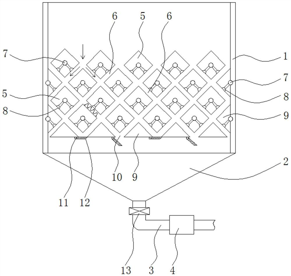
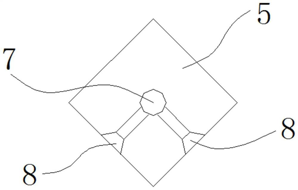
[0017] Such as figure 1 and figure 2 Shown, a kind of efficient settling tank comprises settling tank 1, and the bottom of this settling tank 1 is set as the sedimentation tank 2 of funnel shape, and the bottom of this settling tank 2 is also equipped with suction pipe 3, on the suction pipe 3 A dredge pump 4 is installed; a number of uniformly arranged horizontal pipes 5 are also arranged in the sedimentation tank 1; 5 is set to be installed with a 45° rotation, the four corners are located at the upper, lower, left, and right positions respectively, and the horizontal tubes 5 are ar...


PUM


Abstract

The invention discloses an efficient sedimentation tank, which comprises a sedimentation tank body, a funnel-shaped sedimentation tank is arranged at the bottom of the sedimentation tank body, a mud suction pipe is further installed at the bottom of the sedimentation tank body, and a mud suction pump is installed on the mud suction pipe; a plurality of horizontal pipes which are uniformly distributed are also arranged in the sedimentation tank; wherein the horizontal pipe is of a solid structure and is arranged above the sedimentation tank, the horizontal pipe is of a square pipe body structure, the horizontal pipe is arranged to rotate by 45 degrees, four corner points of the horizontal pipe are located at the upper, lower, left and right positions respectively, and the horizontal pipe isarranged to be arranged in an up-down staggered array mode. When the device is used for settling, sludge at the upper part naturally settles into the settling tank at the lower part from the sludge discharge slideway, so that the settled sludge cannot generate a reverse settling phenomenon under the blocking of the horizontal pipes arranged at the upper part in the process of refilling sewage orpumping away the sludge at the bottom, and the settling work can be efficiently finished with high quality.

Description

technical field [0001] The invention relates to the technical field of environmental protection equipment, in particular to a high-efficiency sedimentation tank. Background technique [0002] The sedimentation tank in the existing structure usually adopts shallow pond theory for sedimentation, and its working principle is to realize the separation of water body and sludge by installing inclined plates, inclined pipes, horizontal pipes or labyrinth sedimentation structures in the sedimentation tank; After the sedimentation tank in the structure settles the sludge, when the sludge needs to be pumped out or the sewage is refilled, it often causes the disturbance of the water body in the sedimentation tank, which seriously affects the sedimentation efficiency and quality of the sedimentation tank; in addition, various In the tank where the pipeline is deposited, a layer of retardation film will appear on the surface of the pipeline over time, which will not only cause corrosion ...

Claims


Application Information

Patent Timeline
Patent Type & Authority Applications(China)
IPC IPC(8): B01D21/24B08B9/093
CPCB01D21/245B01D21/2405B01D21/2472B08B9/093
Inventor 邵渊峰张盘新王菲周卫科
Owner UNIVERSAL ENVIROMENTAL PROTECTION EQUIP YIXING CITY
Learn More