Clamping device
A clamping device and body clamping technology, which is applied to washing devices, other drying devices, window decorations, etc., can solve the problems of poor ventilation and sunshade effects of curtains, and achieve reduced curtain swing and good Sunshade effect, good ventilation effect
- Summary
- Abstract
- Description
- Claims
- Application Information
AI Technical Summary
Problems solved by technology
Method used
Image

Examples
Embodiment 1
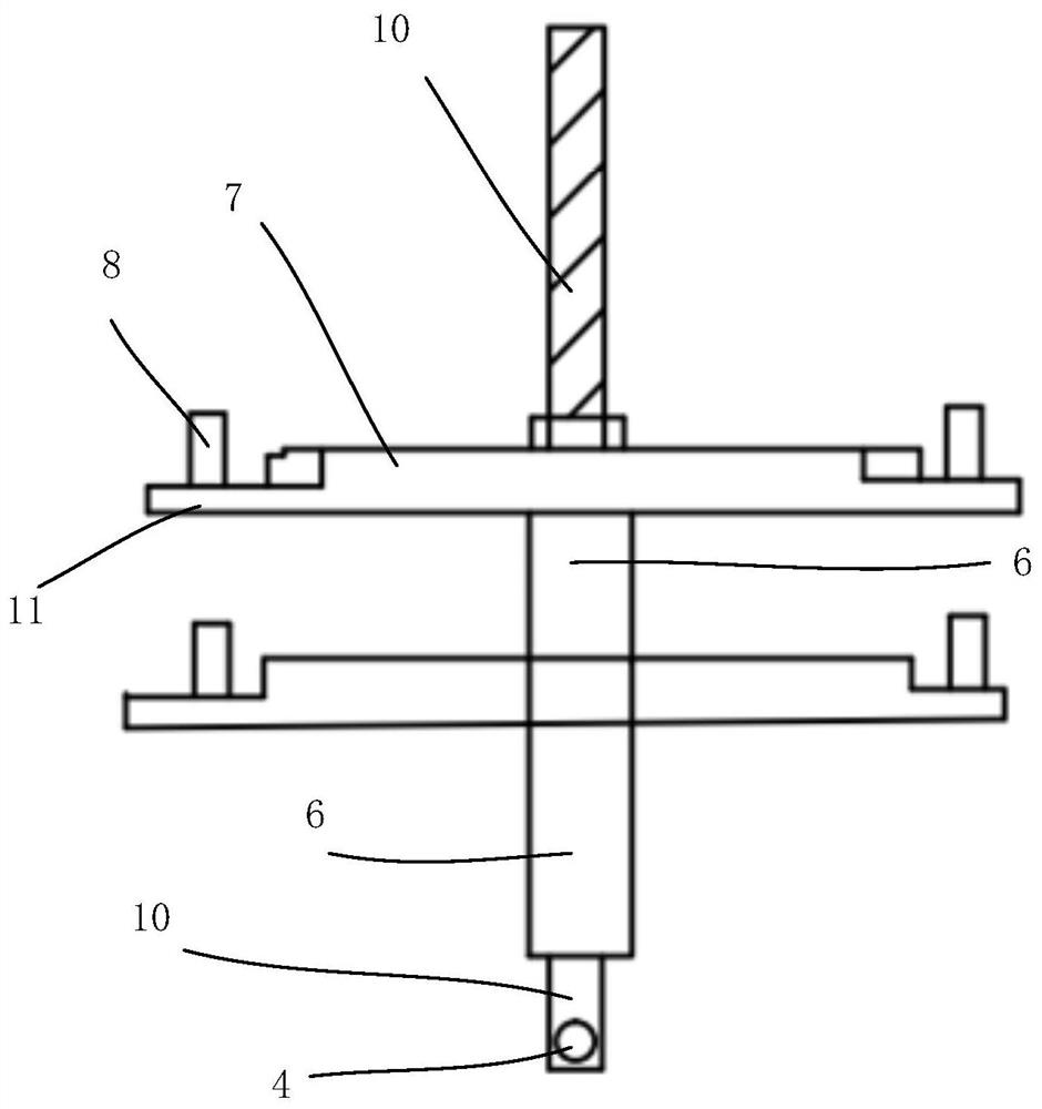
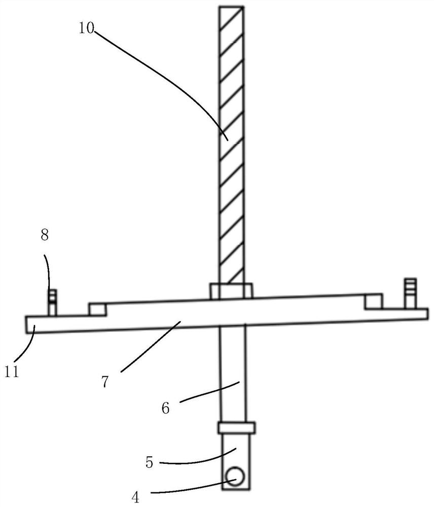
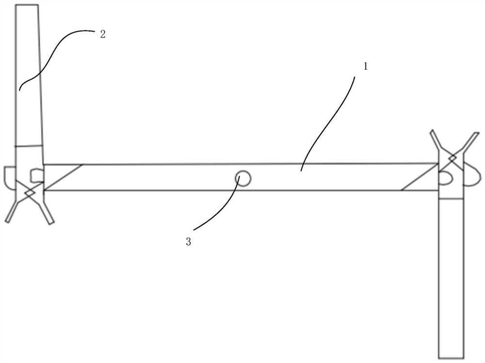
[0040] Such as Figure 1 to Figure 18As shown, a clamping device in this embodiment includes a Z-shaped clamp body 1, a sleeve 6, a first stud 8, a screw rod 10, a clamping assembly 2 and a fixed table assembly, and the Z-shaped clamp body 1 has two left and right sides. A first stud 8 is respectively fixed at each end, a plurality of Z-shaped clip bodies 1 are sleeved on the screw rod 10, at least one sleeve 6 is sleeved on the screw rod 10, and the upper end and the lower end of the sleeve 6 are respectively fixed with a The Z-shaped clamp body 1, the screw rod 10 is inserted on the fixed table assembly, and the left and right ends of the Z-shaped clamp body 1 are respectively provided with a clamping component 2, and the clamping component 2 rotates with the Z-shaped clamp body 1 through the first stud 8 connect.
[0041] Wherein, the clamping assembly 2 that is arranged on the left and right ends of the Z-shaped clip body 1 and the Z-shaped clip body 1 form a "Z" shape; t...
Embodiment 2
[0044] Such as Figure 1 to Figure 5 As shown, a clamping device in this embodiment includes all the technical features in Embodiment 1. In addition, the Z-shaped clamp body 1 includes a clamp body 7 and an adjustment plate 11, and the left and right ends of the clamp body 7 An adjusting plate 11 is respectively provided, and the center position of the adjusting plate 11 is welded with a first stud 8, and a clamping body 7 is respectively fixed on the upper end and the lower end of the sleeve 6, and the clamping assembly 2 is rotationally connected with the adjusting plate 11. The plate 11 is rotatably connected to the clamping assembly 2 through the first stud 8 , and the screw 10 is detachably connected to the fixed table assembly through the clamp body 7 .
[0045] Preferably, the Z-shaped clip body 1 also includes an adjustment hole 12, and the adjustment plate 11 is provided with a plurality of adjustment holes 12, and the plurality of adjustment holes 12 are evenly distr...
Embodiment 3
[0050] Such as Figure 14 As shown, a clamping device in this embodiment includes all the technical features in Embodiment 1. In addition, the fixed table assembly includes a first fixing plate 25, a first fixing hole 26, a first fixing rod 27 , the first screw groove 28 and the second socket 29, the screw 10 is inserted into the first screw groove 28 and is detachably connected with the first screw groove 28, the first screw groove 28 is provided with a second socket 29, the first socket 4 and the second socket 29 are connected by bolts, the upper end of the first fixing rod 27 is fixed with a first screw groove 28, the lower end of the first fixing rod 27 is fixed with a first fixing plate 25, and the first fixing plate 25 is provided with at least one first A fixing hole 26.
[0051] The beneficial effects in this embodiment are: the structure of this fixed platform assembly can be applied to curtains without a window sill, and the setting of the first fixing plate 25 and ...
PUM
 Abstract
Description
Claims
Application Information
 - R&D Engineer
- R&D Manager
- IP Professional
- Industry Leading Data Capabilities
- Powerful AI technology
- Patent DNA Extraction
Browse by: Latest US Patents, China's latest patents, Technical Efficacy Thesaurus, Application Domain, Technology Topic.
© 2024 PatSnap. All rights reserved.Legal|Privacy policy|Modern Slavery Act Transparency Statement|Sitemap