A cleaning device for floor drain

A technology for cleaning devices and floor drains, applied to water supply devices, separation methods, filtration and separation, etc., can solve the problems of inefficiency and unsanitary, and achieve the effect of efficient cleaning and hygienic washing process

Active Publication Date: 2021-12-07
TAISHAN UNIV
View PDF7 Cites 0 Cited by
  • Summary
  • Abstract
  • Description
  • Claims
  • Application Information

AI Technical Summary

Problems solved by technology

At present, there is no special floor drain cleaning device, and only traditional buckets, brushes, rubber gloves, etc. can be used for cleaning, which is neither hygienic nor efficient

Method used


Image

  • A cleaning device for floor drain
  • A cleaning device for floor drain
  • A cleaning device for floor drain

Examples


Embodiment Construction

[0075] The embodiments described below by referring to the figures are exemplary only for explaining the present invention and should not be construed as limiting the present invention.

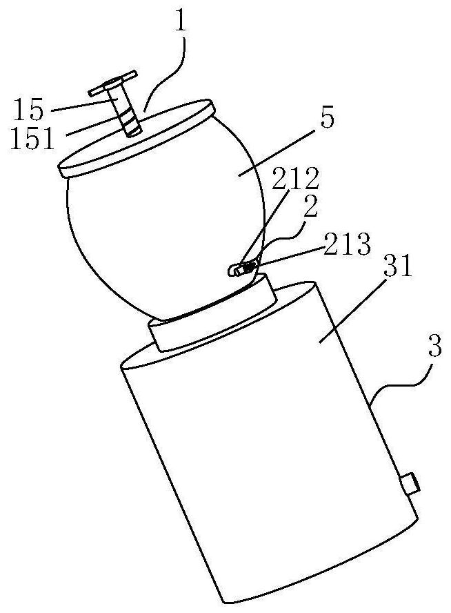
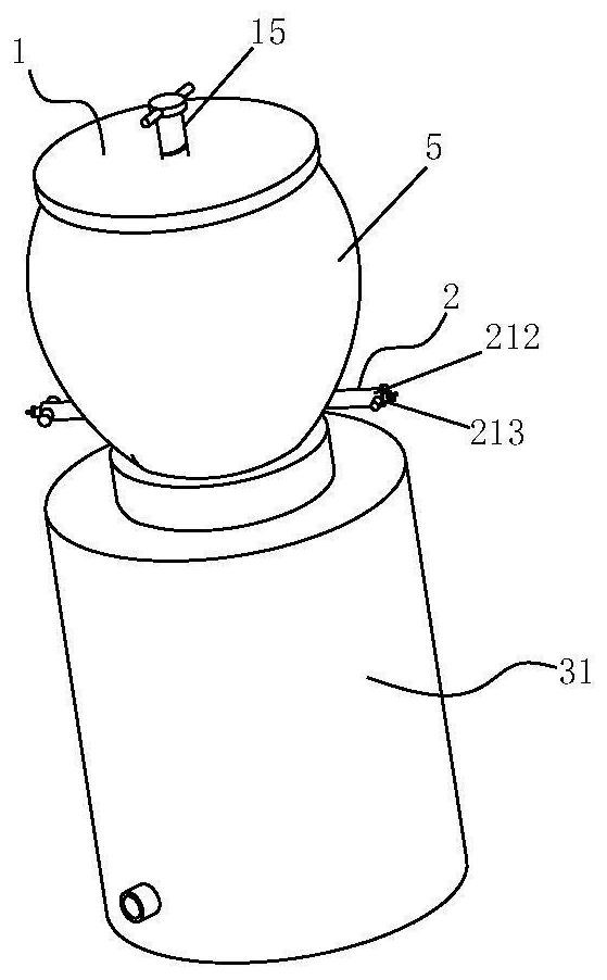
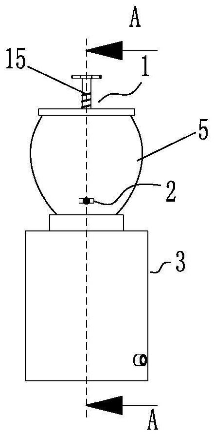
[0076] Please refer to Figure 1 to Figure 11 , The present invention proposes a cleaning device for floor drains, which includes a grasping mechanism 1 , an overturning mechanism 2 and a flushing mechanism 3 . The invention is applied to the cleaning of the floor drain, especially to the cleaning of the filter screen of the floor drain.

[0077] The grasping mechanism 1 is used to grab the filter screen of the floor drain, and release it after moving to a preset position; it is also used to take out the cleaned filter screen from the preset position, and move it to the floor drain; The overturning mechanism 2 is used to clamp the filter screen placed on the preset position, and turn the filter screen 180 degrees along the horizontal line; the overturning mechanism 2 is located above the flu...


PUM


Abstract

The invention discloses a cleaning device for a floor drain, which includes a grabbing mechanism, which is used to grab the filter screen of the floor drain, and release it after moving to a preset position; At the preset position, take out the cleaned filter screen and move it to the floor drain; the turning mechanism is used to clamp the filter screen placed at the preset position, and turn the filter screen 180 degrees along the horizontal line The flushing mechanism, the turning mechanism is located above the flushing mechanism, the flushing mechanism is connected with a water outlet pipe, and the water outlet pipe is located above the turning mechanism; the water outlet pipe is used to filter from top to bottom Net spray. The invention can facilitate the cleaning of the floor drain, especially the filter screen of the floor drain.

Description

technical field [0001] The invention relates to a clamp, in particular to a cleaning device for floor drains used in processing straight arm pin holes. Background technique [0002] Floor drains and water leaks are easy to block and smell, and the floor drains on the market (shallow water-sealed floor drains, bouncing floor drains, etc.) are difficult to clean. People are often reluctant to touch, clean and maintain the floor drains with their hands. It is reported that a company in Beijing has invented and disclosed a floor drain device that is easy to clean up stains, including a floor drain body, sleeve one and sleeve two, the bottom of the floor drain body is provided with the sleeve one, and the bottom of the sleeve one is provided with sleeve two , the floor drain body is composed of a network grid, a pinch plate and a channel. A cleaning device is installed inside the pinch plate on one side. A support rod is installed inside the cleaning device. The top is provided ...

Claims


Application Information

Patent Timeline
Patent Type & Authority Patents(China)
IPC IPC(8): E03F5/04B01D29/01B01D29/96
CPCE03F5/0407B01D29/01B01D29/96
Inventor 苏海霆董天燕郑利娜马倩
Owner TAISHAN UNIV
Why Eureka
Try Eureka