
Socket for dialyzer

Inactive Publication Date: 2005-06-21
ESTECH
View PDF16 Cites 29 Cited by
  • Summary
  • Abstract
  • Description
  • Claims
  • Application Information

AI Technical Summary

Benefits of technology

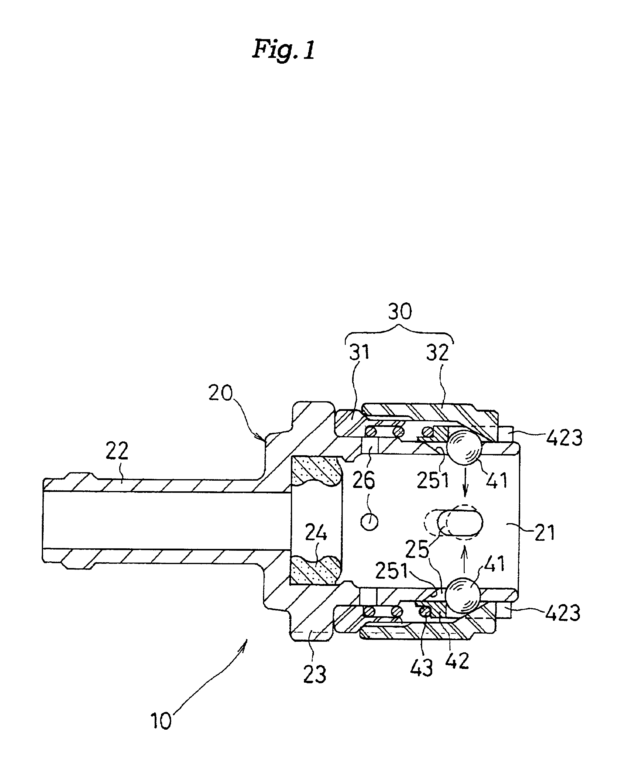
[0014]The locking ball, which is pressed by the holder, is guided along a tapered surface of the outer sleeve, so that the locking ball is spring-biased in the locking direction from the inner wall of the coupling part and is engaged with an annular groove of the plug. Thus, the locked state of the plug and the socket can be maintained.
[0017]In addition, when attaching the socket to the plug of the dialyzer, the locking ball is once put in a free state, pressed by the outer periphery of the plug to be shifted outwardly, and then engaged with the annular groove of the plug. Associated with this movement, the holder is once retracted and then moves forward, and if in a normal locked position, the holder is in a state where the protrusion of the holder protrudes from the front end surface of the outer sleeve by a predetermined length. By visually checking the protruding length of the protrusion, whether the locked state is reliable or not can be verified. And if the protrusion and the front end surface of the outer sleeve are classified by different colors for discrimination, the locked state can be easily verified visually.
[0021]Furthermore, if a front end portion of the holder constitutes a protrusion externally protruding, when cleaning the socket, the locking ball can be put in a released state (floating state) by pressing the protrusion to retract the holder, and therefore, the entire surface of the locking ball can be completely cleaned.
[0025]As is apparent from the construction described above, in the method for cleaning a socket for a dialyzer according to this invention, the socket is fitted into the socket accommodation room of the adapter main body in an enveloped state for cleaning. Accordingly, unlike the conventional adapters, there is no disadvantage that the overlapped part (connection part) cannot be cleaned, and the entire inner wall of the socket can be completely cleaned. In addition, compared with the dipping method, a higher cleanability can be attained due to the circulation of the cleaning solution.

Problems solved by technology

In particular, in the case of a dialysis filtration system based on a scheme of injecting blood into the dialyzer, if there is any germ or toxin in the dialysate, a problem arises that a patient is adversely affected, for example, becomes feverish, so that when the socket 4 is to be repeatedly used, it is actually desired that the socket 4 has a high cleanability.
Thus, a problem has been pointed out that when the socket 4 is attached to or removed from the plug, two operations are needed respectively, which degrades the operability when connecting the socket 4.

Method used


Image

  • Socket for dialyzer
  • Socket for dialyzer
  • Socket for dialyzer

Examples


Embodiment Construction

[0037]An embodiment of a socket for a dialyzer according to the present invention and a method for cleaning the same will be described in detail below with reference to the accompanying drawings.

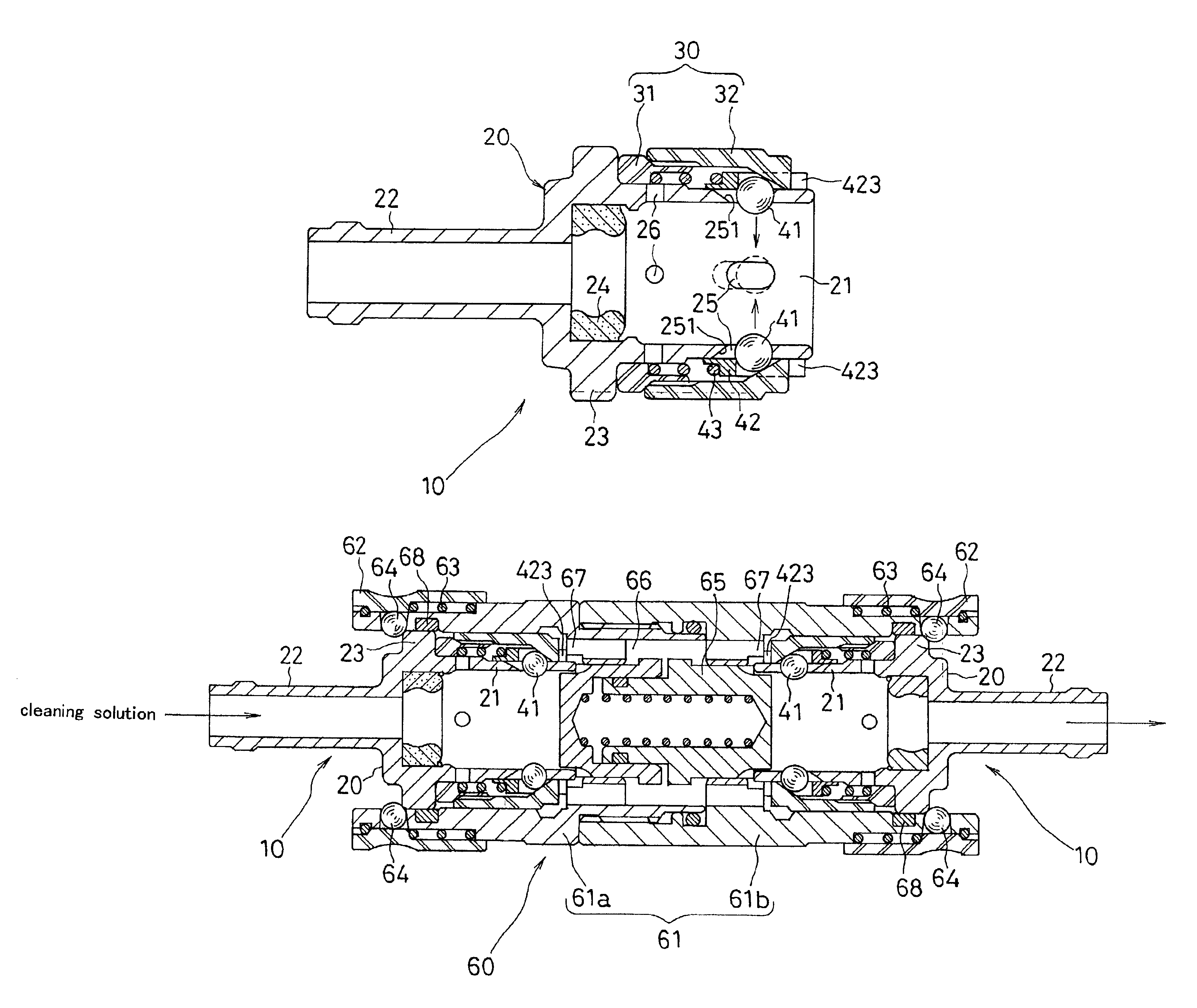
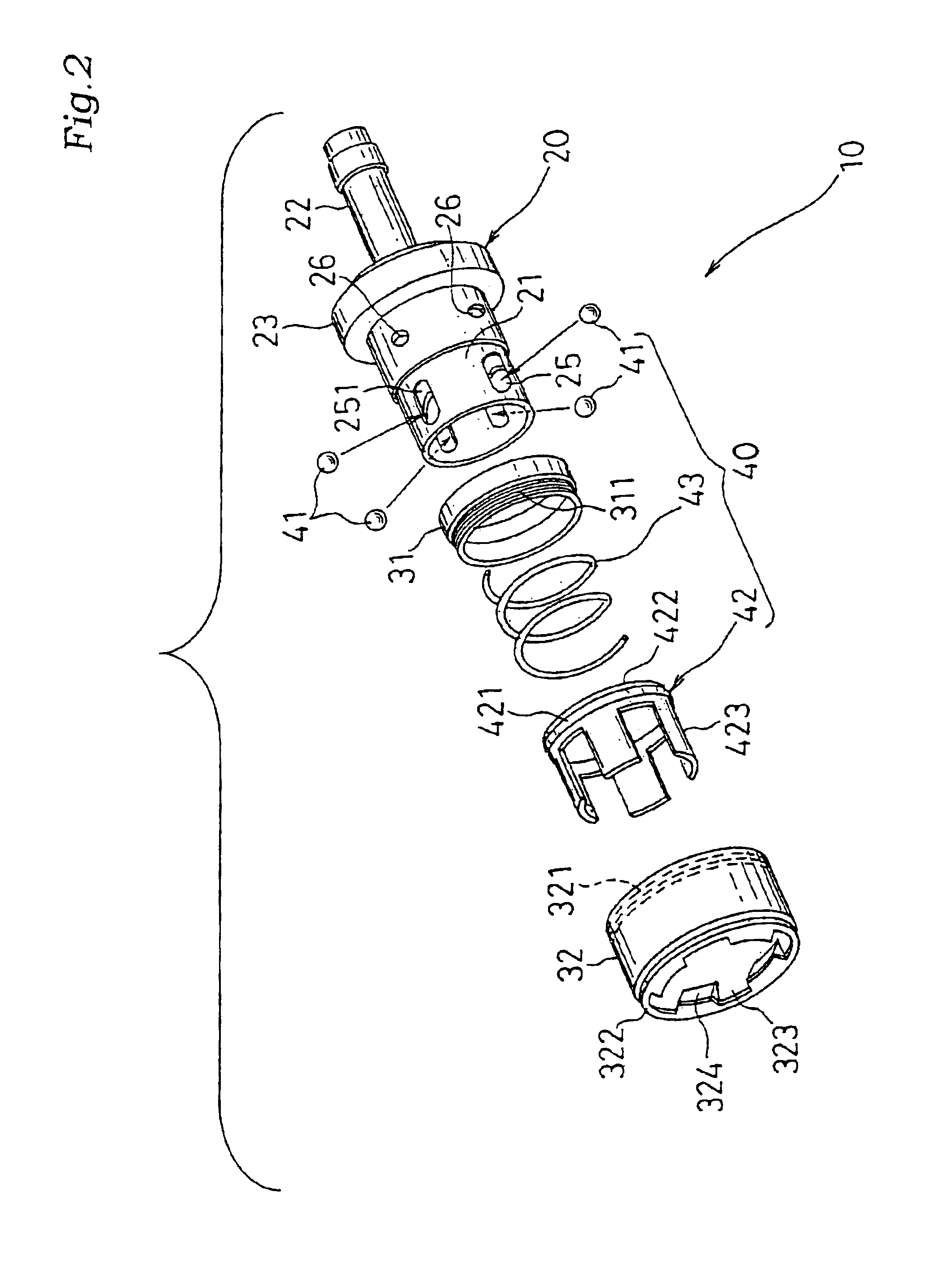
[0038]FIG. 1 is a cross-sectional view of a construction of a socket for a dialyzer according to this invention, and FIGS. 2 and 3 are an exploded perspective view of a construction of the socket and a cross-sectional view thereof before being assembled, respectively. FIG. 4 illustrates connection of the socket for a dialyzer according to this invention to a plug of the dialyzer, FIG. 5 is a cross-sectional view of a construction of a cleaning adapter used when cleaning the socket for a dialyzer according to this invention, FIG. 6 is an end view of the cleaning adapter viewed from the socket to be attached thereto, FIG. 7 illustrates the socket according to this invention attached to the cleaning adapter, and FIG. 8 illustrates an operation of a method for cleaning the socket for a dialyzer ...


PUM


Abstract

A spring-biased holder 42 for pressing a locking ball (41) is accommodated between an outer sleeve (30) fitted onto an outer surface of a coupling part (21) of a coupler main body (20) and the outer surface of the coupling part (21) so as to be capable of moving back and forth. A coupler (10) can be attached to a plug (51) of a dialyzer (50) easily with a single operation by moving the holder (42) back and forth. In cleaning using a cleaning adapter (60), the coupler (10) is attached to the adapter (60) while releasing the locking ball (41) with a pressing protrusion (67) of the adapter (60), so that the inside of the coupling part (21) can be surely cleaned.

Description

TECHNICAL FIELD[0001]The present invention relates to a socket for a dialyzer that connects a plug of a dialyzer and a dialysate tube and a method for cleaning the same, in particular, to a socket for a dialyzer that can be attached to or removed from the plug with a single operation to provide an increased operability in connecting the socket, and surely prevent contamination when the socket is attached to the plug of the dialyzer by virtue of an internal component thereof with an improved cleanability, such as a locking ball or spring in the socket, and a method for cleaning the socket.BACKGROUND ART[0002]Typically, as shown in FIG. 9, a dialyzer 1 has a cylindrical container containing a large number of hollow fiber semipermeable membrane capillaries, and allows exchange of blood in a patient body by passing the blood extracted from the patient body through the capillaries and supplying a dialysate, such as a physiologic saline, to the exterior of the capillaries to extract body ...

Claims


Application Information

Patent Timeline
IPC IPC(8): A61M39/10A61M39/00F16L37/00F16L37/23A61M1/16B08B9/027A61L2/18A61M1/14B01D61/30
CPCA61M39/1011F16L37/23A61M1/16A61M2039/1066A61M2039/1077A61M2039/1027
Inventor FUMIOKA, HIROYUKI
Owner ESTECH
Learn More