Solids recovery using cross-flow microfilter and automatic piston discharge centrifuge

a technology of automatic piston discharge and microfilter, which is applied in the direction of centrifuges, membranes, multi-stage water/sewage treatment, etc., can solve the problems of damage, poor yield, and sensitive chemical or biological substances such as intact cells,

Inactive Publication Date: 2007-05-24
CARR ROBERT BRET
View PDF54 Cites 32 Cited by
  • Summary
  • Abstract
  • Description
  • Claims
  • Application Information

AI Technical Summary

Benefits of technology

[0027] In one embodiment, the separator also comprises a first passage partially disposed within the valve piston. The first passage can cooperate with the second valve member, for example, at the uppermost end of the valve piston, and a second passage partially disposed within the valve piston. Preferably, when a valve member of the first passage is closed, fluid introduced through a port for the second passage enters the bowl below the lower portion of the piston. Fluid introduced through the port increases fluid pressure in the bowl below the lower portion of the piston relative to that above the upper portion thereof so as to cause the piston to move toward an upper end of the bowl.

Problems solved by technology

For example, some separators may not be capable of completely discharging solids that are sticky, which can result in poor yields.
A poor yield can be especially problematic for high-value solids such as those encountered in pharmaceutical processes.
Traditional separators also subject a feed material to very high shear forces when accelerating the material to the rotational speed of the bowl, which can damage, for example, sensitive chemical or biological substances such as intact cells.
Still, other separators do not provide a convenient means by which to handle and recover sensitive solids.
Separators that require such operator intervention often suffer from contamination problems.
Furthermore, some separators employ numerous mechanical components to facilitate solids recovery, which can affect separator durability.
Such components are usually external to the separator or in the form of add-on equipment that poses both size and compatibility issues.
Conventional separators also tend to be difficult to clean or sterilize without significantly increasing maintenance costs.
Backwashing is often necessary to reduce the concentration of accumulated solids on the filter membrane, causing delays in processing.
Such mechanisms previously have resulted in removed solids wetted by a relatively significant amount of retentate.
The provision of pretreatment liquid and such a solids removal mechanism result in increased processing time, complexity, and cost while providing suboptimal solids drying performance.

Method used


Image

  • Solids recovery using cross-flow microfilter and automatic piston discharge centrifuge
  • Solids recovery using cross-flow microfilter and automatic piston discharge centrifuge
  • Solids recovery using cross-flow microfilter and automatic piston discharge centrifuge

Examples


Embodiment Construction

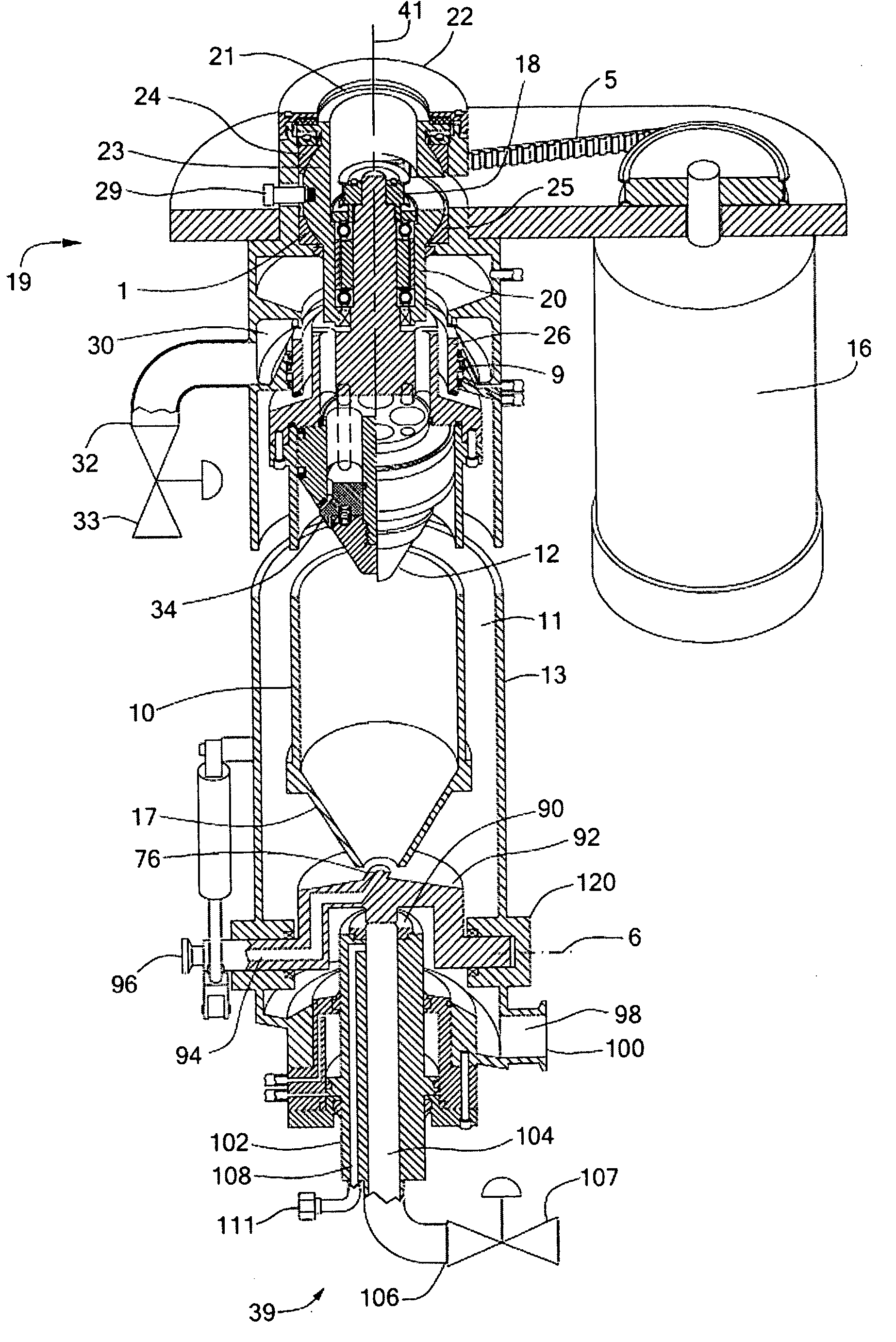
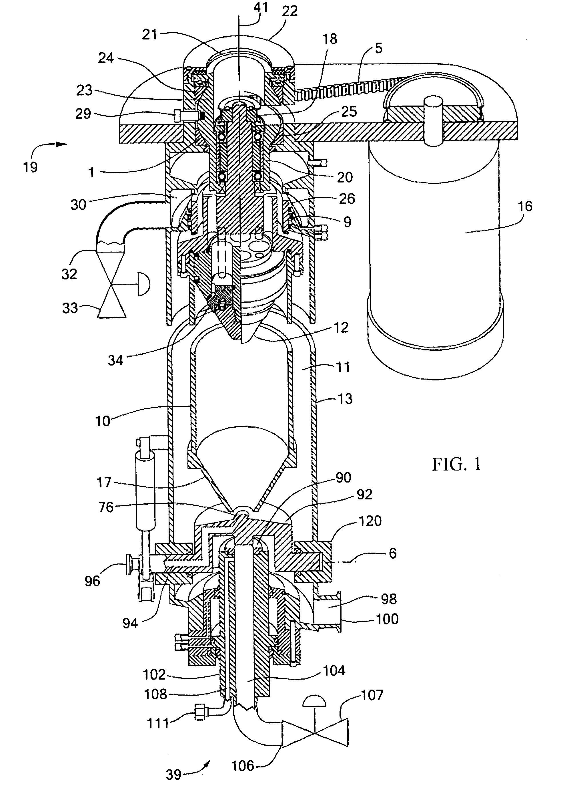
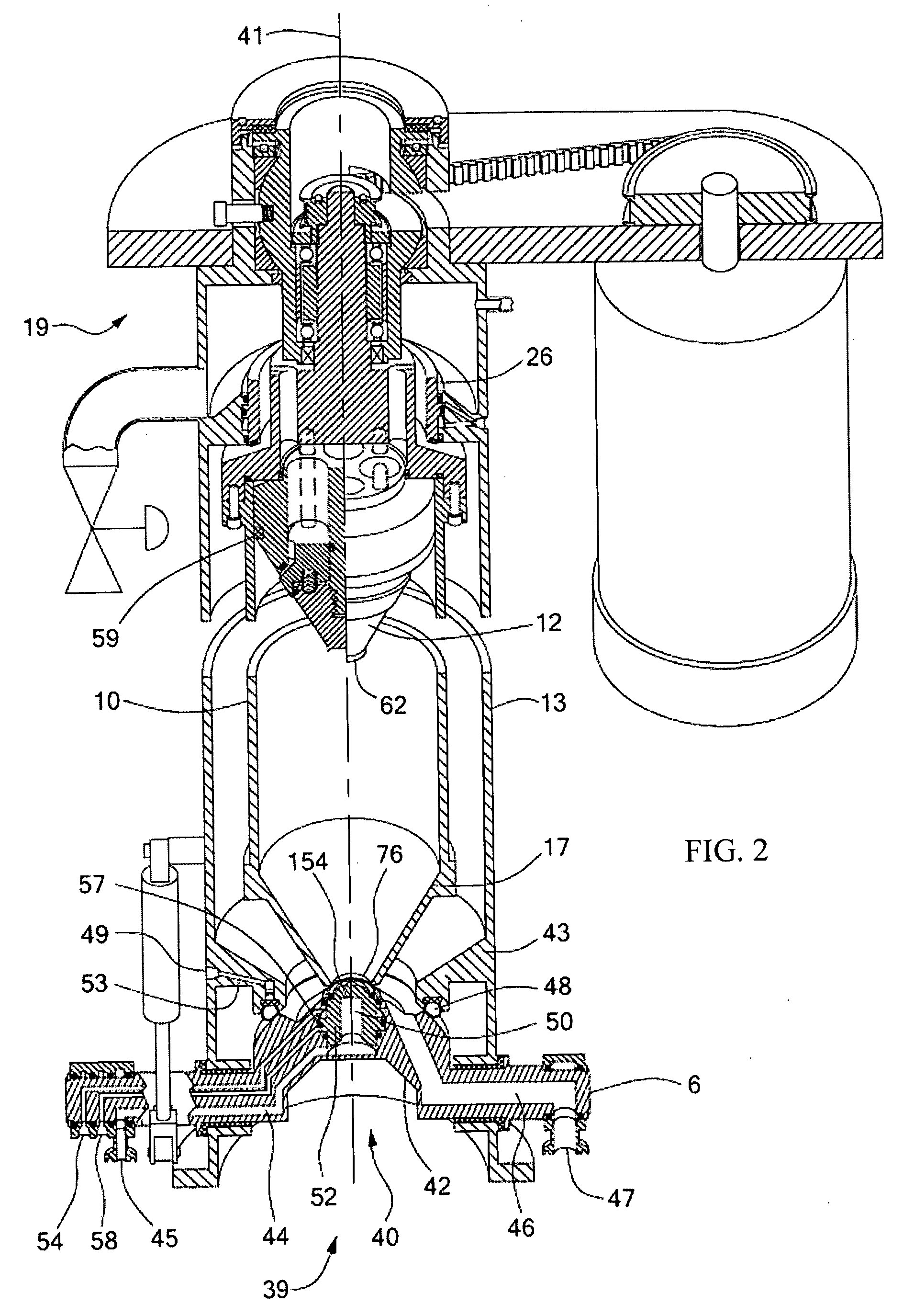
[0050]FIG. 1 shows a centrifugal separator in vertical section, with a middle portion removed so as to illustrate a horizontal section as well. The centrifugal separator includes a cylindrical separator bowl 10 mounted in a central region 11 of a separator housing 13. Preferably, the separator bowl can be of a length that is greater than a diameter thereof. By having the length of the bowl longer than its diameter, “end effects” in the bowl can be minimized with respect to the bowl's internal volume. In general, end effects can be caused by fluid eddies along any of the angled portions within the interior of the bowl and, particularly, near the ends thereof. In one embodiment, the separator bowl 10 can be a cylindrical type bowl having a relatively small diameter D and a length L such that the ratio of L / D is approximately 5 / 1 or greater. Such a ratio of L / D tends to prevent axial waves from developing within the bowl as such waves substantially dissipate as they travel the length o...


PUM

PropertyMeasurementUnit
of rotationaaaaaaaaaa
concentrationaaaaaaaaaa
turbidityaaaaaaaaaa

Abstract

In a system for combined centrifugation and microfiltration, retentate from a cross-flow microfilter is fed to an automatic piston discharge centrifuge for solids removal, thereby enhancing the efficiency of both processes. The centrifuge includes a cylindrical bowl having a conical lower end with an opening through which feed liquid is injected. Solids separate from the feed liquid and accumulate along the inner surface of the bowl as the bowl rotates at high speed. A microfiltration membrane can be added to improve solids retention in the bowl and provide a filtered centrate. During solids discharge, a piston is urged downward along a vertical axis. The downward movement of the piston forces accumulated solids from the bowl via the opening in the conical lower end thereof.

Description

CROSS REFERENCE TO RELATED APPLICATIONS [0001] This application is a continuation-in-part of co-pending U.S. application Ser. No. 11 / 218,280, filed Sep. 1, 2005 and a continuation-in-part of International Application No. PCT / IB2006 / 002411 filed Aug. 25, 2006. This application claims the priority of U.S. Provisional Application No. 60 / 742,558 filed Dec. 5, 2005 and U.S. Provisional Application No. 60 / 756,381 filed Jan. 4, 2006. Each of the foregoing related applications is hereby incorporated by reference.BACKGROUND OF THE INVENTION [0002] Many different types of centrifugal separators are known for separating heterogeneous mixtures into components based on specific gravity. Typically, a heterogeneous mixture, which may also be referred to as feed material or liquid, is injected into a rotating bowl of a centrifugal separator. The rotating bowl spins at high speeds and forces components of the mixture that have a high specific gravity to separate therefrom by sedimentation. As a resu...

Claims


Application Information

Patent Timeline
Patent Type & Authority Applications(United States)
IPC IPC(8): B01D65/00
CPCB01D21/0012B04B11/05B01D21/245B01D61/147B01D61/18B01D61/20B01D2311/2676B04B5/10B04B11/04B04B2005/0485B01D21/302B01D21/34B01D21/262B01D21/32B01D21/2444
Inventor CARR, ROBERT B.
Owner CARR ROBERT BRET
Why Eureka
Try Eureka