Spray nozzle cleaning method and warm water washlet device

A nozzle and cleaning technology, which is applied in the field of warm water toilet seat device and nozzle cleaning, can solve the problems of accelerated aging, user electric shock, falling off, etc., and achieve the effect of sufficient cleaning and high sterilization level

Active Publication Date: 2013-05-08
PANASONIC APPLIANCES CHINA CO LTD +1
View PDF5 Cites 30 Cited by
  • Summary
  • Abstract
  • Description
  • Claims
  • Application Information

AI Technical Summary

Problems solved by technology

However, due to the relatively complex surface structure of the nozzle body and the human body cleaning port, there are many gaps at the front end of the nozzle body that are easy to breed bacteria and are not easy to be cleaned. The aforementioned structure of using nozzle cleaning port to spray water to clean the nozzle body, Due to the relationship between water pressure or flow rate, the water flowing out of the nozzle cleaning port cannot fully flow through the front end of the nozzle body, especially the front end of the human body cleaning port, so it cannot clean the gaps and dead ends of the nozzle body, and the nozzle cannot be fully cleaned main body
In addition, the structure does not control the water temperature of the water used to clean the nozzle body, which is also the cause of insufficient cleaning
[0009] Although the lighting device can provide a relatively sufficient cleaning effect, due to the need to supply power to the light source of the lighting device, once the light source is poorly insulated, it will bring safety problems such as electric shock to the user, and there is a potential safety hazard; The light of the sterilizing wavelength irradiates the nozzle body, and it will also accelerate the aging of the parts (especially plastic parts) such as the nozzle body and its surroundings that can be irradiated by light. Long-term use will cause cracks on the surface of the nozzle body and its surroundings. , or even unfavorable conditions such as shedding

Method used


Image

  • Spray nozzle cleaning method and warm water washlet device
  • Spray nozzle cleaning method and warm water washlet device
  • Spray nozzle cleaning method and warm water washlet device

Examples


Embodiment approach 1

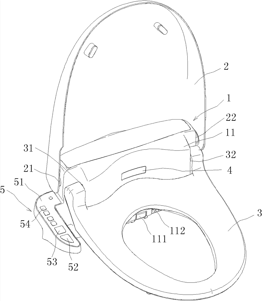
[0050] Such as Figure 1~2 As shown, the warm water toilet seat device provided by the present invention includes:

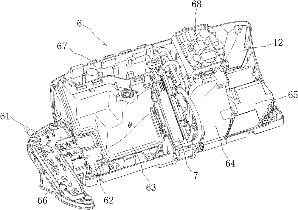
[0051] The main body shell 1 includes a main body cover 11 and a main body bottom plate 12 for supporting and protecting internal components;

[0052] The toilet cover 2 is rotatably mounted on the main body cover 11 through two rotating shafts 21 and 22 (not shown), and the toilet cover 2 can perform opening and closing rotation around the two rotating shafts 21 and 22;

[0053] The toilet ring 3 is rotatably mounted on the main body cover 11 relative to the rotating shafts 21 and 22 through two rotating shafts 31 and 32 (not shown). The toilet ring 3 is used to support the weight of the user and can rotate around the Rotating shafts 31 and 32 are turned on and off;

[0054] The seating sensor 4 is installed on the front part of the main body cover 11 close to the back and upper part of the toilet ring 3, and is used to detect whether a user is seated;

[00...

Embodiment approach 2

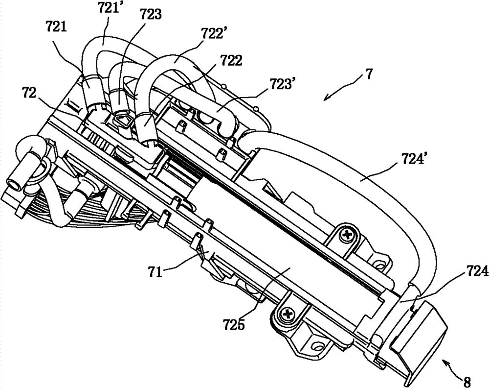
[0081] Such as Figure 8-11 As shown, the principles and effects of the warm water toilet seat device, nozzle assembly 7, bracket 71 and baffle 8 of this embodiment are basically the same as those of the warm water toilet seat device, nozzle assembly 7, bracket 71 and baffle 8 of Embodiment 1, and the baffle 8 It is also movably connected to the front end of the bracket 71, the difference is:

[0082] The baffle 8 is cylindrical, and the front end of the baffle 8 has an opening 86 for the nozzle main body 72 to enter and exit, so that the baffle 8 is rotatably connected to the front end of the bracket 70 around the axial direction of the nozzle main body 72, such as through the baffle Between the inner peripheral surface of 8 and the outer peripheral surface of bracket 71, there is provided a concave-convex structure extending along the circumferential direction with clearance fit to make the two rotatably engaged, so that the reflective part 80 of the baffle 8 is constituted ...

Embodiment approach 3

[0090] see you again Figure 10 , 11 The principles and effects of the warm water toilet seat device, nozzle assembly 7, bracket 71 and baffle 8 of this embodiment are basically the same as those of the warm water toilet seat device, nozzle assembly 7, bracket 71 and baffle 8 of Embodiment 2. The difference is: the baffle plate 8 is fixedly connected to the front end of the bracket 71, and the nozzle body 72 moves in the axial direction to change the distance between the two in the axial direction, that is, the length of the vector, thereby changing the first water flow 91 direction of reflection.

[0091] The fixed connection mentioned in this embodiment can make the baffle 8 detachably connected to the bracket 71 , and of course the baffle 8 can also be connected to the bracket 71 in a non-detachable way such as welding or integral molding.

[0092] In this embodiment, the reflective portion 80 of the baffle 8 includes a reflective portion 80 that changes along the normal ...


PUM


Abstract

The invention discloses a spray nozzle cleaning method which is used for cleaning a spray nozzle body of a spray nozzle assembly of a warm water washlet device. The method includes a fixed point cleaning step which includes that a baffle board of the spray nozzle assembly is located at a preset position relative to the spray nozzle body, a human body cleaning port arranged on the spray nozzle body sprays first water flow which is reflected to be along a preset direction by a reflection portion on the inner side of the baffle board, and the reflected first water flow is used for cleaning the spray nozzle body. The invention further discloses the warm water washlet device for implementing the spray nozzle cleaning method. The warm water washlet device comprises the spray nozzle assembly which comprises a bracket and the spray nozzle body installed on the bracket, and the baffle board with the reflection portion on the inner side is arranged on the bracket; and according to the reflection portion, under the condition that the relative position between the spray nozzle body and the baffle board is changed, the reflection direction of the first water flow sprayed by the human body cleaning port arranged on the spray nozzle body is changed.

Description

technical field [0001] The invention relates to a toilet seat device, in particular to a warm water toilet seat device and a nozzle cleaning method. Background technique [0002] At present, warm water toilet seat devices that can flush the user's lower body parts such as the buttocks and the front part of women after the user defecates have widely appeared. [0003] The warm water toilet seat device includes a main body part and a control part. The main part includes: a water tank, which stores and heats water for washing the lower part of the human body; a nozzle assembly, which includes a bracket, a nozzle body supported on the bracket and having a human body cleaning port at the front end, and a driving device for driving the nozzle body to telescopically move; The toilet seat and the toilet ring are respectively rotatably connected to the main body. The control part includes: an operation part, through which the user inputs instructions according to needs; and a contr...

Claims


Application Information

Patent Timeline
Patent Type & Authority Applications(China)
IPC IPC(8): E03D9/08
Inventor 胡一凡周燕文国木靖博
Owner PANASONIC APPLIANCES CHINA CO LTD
Why Eureka
Try Eureka