
Method for sonic cleaning of reactor with reduced acoustic wave cancellation

a reactor and acoustic wave cancellation technology, applied in the direction of cleaning hollow objects, liquid cleaning, chemistry apparatus and processes, etc., can solve the problems of weak spots at the area, adversely affecting the properties of polymer products, falling off the reactor wall, clogging the distributor plate, etc., to reduce the time-average effect of weak spots and reduce or eliminate the time-average

Inactive Publication Date: 2006-06-22
CAI PING +1
View PDF9 Cites 15 Cited by
  • Summary
  • Abstract
  • Description
  • Claims
  • Application Information

AI Technical Summary

Benefits of technology

[0017] In a class of embodiments, the invention is a method for sonically cleaning a surface of a reactor (e.g., the freeboard surface of a fluidized bed reactor useful for the production of polyolefins, or a surface of a reactor of another type) using a set of sonic sources, said method including the steps of: (a) operating the set of sources in an initial operating mode to cause sonic waves incident on a surface of the reactor to produce a first set of weak spots on the surface of the reactor; and (b) after step (a), operating the set of sources in at least one other operating mode to cause sonic waves incident on the surface to produce a second set of weak spots on the surface that does not coincide with the first set of weak spots. This can reduce the time-averaged effect of weak spots at each location on the surface to prevent any location on the surface from being inadequately cleaned, and can reduce or eliminate the time-averaged effect of all or some of the weak spots in the first set. In each individual one of the operating modes, each sonic source operates with fixed frequency while active, and each sonic source in the set can operate either intermittently (e.g., can be sequentially shut off and on) or continuously (e.g., to emit sonic waves having constant or time-varying intensity) or can remain off (inactive).
[0018] The set of sonic sources typically includes more than one sonic source but in some embodiments consists of a single sonic source. The occurrence of weak spots during sonic cleaning of a reactor can be minimized or prevented in an easily implementable manner in accordance with typical embodiments of the invention. For example, in accordance with some embodiments, the operating mode of a set of sonic sources is varied over time during sonic cleaning of a reactor to reduce (e.g., minimize) acoustic wave cancellation at at least some spots on a surface of the reactor, thereby cleaning the surface more effectively than if acoustic wave cancellation were not reduced by so varying the operating mode.
[0027] In a class of embodiments, adequate (e.g., complete) sonic cleaning of a reactor surface in accordance with the invention is accomplished by one or more of: preventing the occurrence of at least one weak spot on the surface, reducing or minimizing the number of weak spots (and / or the size of at least one weak spot) on the surface, changing the locations of weak spots on the surface (to reduce the time-averaged effect of weak spots at each location on the surface), and reducing the time durations during which weak spots occur at specific locations on the surface. All or some of these effects can contribute to reduction or elimination of cleaning problems that would otherwise result from weak spots, and can achieve adequate cleaning of a reactor's freeboard surface that could not be adequately cleaned by conventional sonic cleaning.
[0028] Other aspects of the invention are methods for determining positions and operating parameters (e.g., duty cycle and output acoustic wave frequency) of each source of a set of sonic sources to be used for sonically cleaning a reactor. Other aspects of the invention are methods including the steps of: (a) determining a position (relative to a reactor) of each source of a set of sonic sources; (b) positioning each said source in the position determined in step (a); and (c) after step (b), sonically cleaning a surface of the reactor including by varying the operating mode of the set of sources to reduce or prevent cleaning problems that would otherwise result from weak spots if the operating mode were not so varied.
[0031] The criterion set forth in equation (A) can be applied at a sequence of different times, and operating parameters can be determined as a result of such multiple applications of the criterion. For example, each performance of the minimization can assume a different value of the wavelength W, or can assume that a different subset of a full set of sonic sources operates (e.g., where a sequence of different subsets of the full set are shut off while the other sources operate continuously or intermittently). The minimization can be performed multiple times to determine a sequence of operating parameter sets (e.g., a sequence that minimizes in some sense the summed or otherwise combined results of all such minimizations). Operation of sonic sources whose operating parameters have been determined in accordance with the criterion of equation (A), e.g., by operating the sources in a sequence of different operating modes, can improve reactor cleaning in any of several different ways, including in one or more of the following ways: by eliminating or minimizing weak spots, by varying the locations of weak spots, and by reducing the time intervals during which weak spots occur at specific locations of the surface to be cleaned.

Problems solved by technology

For example, if acoustic waves from two or more sources propagate directly to an area on a reactor wall, a weak spot can occur at the area as a result of destructive interference between the waves from different individual sources.
However, some fines can become attached to the interior surface of the reactor system, particularly to the freeboard surface, and can contribute to formation of layers (“sheets”) of agglomerated, melted or half-melted, resin and catalyst particles on the interior surface.
Sheets can adversely affect properties of the polymer product.
When sheets become heavy, they can fall off the reactor wall and plug the product discharge system or clog the distributor plate.
Small pieces of sheets can be discharged together with the bulk resin particles and contribute to product quality problems by increasing the gel level of end-use products such as plastic containers and films.
When a reactor is down for cleaning, large amounts of operation time are lost, and the cost of cleaning can itself be high.
U.S. Pat. No. 5,912,309, manifests no recognition that weak spots can occur due to destructive interference between acoustic waves emitted by sonic sources positioned in accordance with its teaching, and does not teach or suggest how to operate sonic sources to minimize or prevent the occurrence of weak spots, or how otherwise to minimize or prevent the occurrence of weak spots.
Practice of the teaching of U.S. Pat. Nos. 5,461,123 and 5,912,309 will not prevent the occurrence of weak spots, and cannot ensure that weak spots will not prevent adequate cleaning of a reactor's freeboard surface or other surface.
The inventors have also recognized that reflected waves have a significant effect on reactor cleaning, and that the occurrence of weak spots on the freeboard surface due to reflected wave cancellation can prevent effective cleaning of the freeboard surface (e.g., polymer material that has become attached to the freeboard surface at weak spots may not be removed effectively).

Method used


Image

  • Method for sonic cleaning of reactor with reduced acoustic wave cancellation
  • Method for sonic cleaning of reactor with reduced acoustic wave cancellation
  • Method for sonic cleaning of reactor with reduced acoustic wave cancellation

Examples


Embodiment Construction

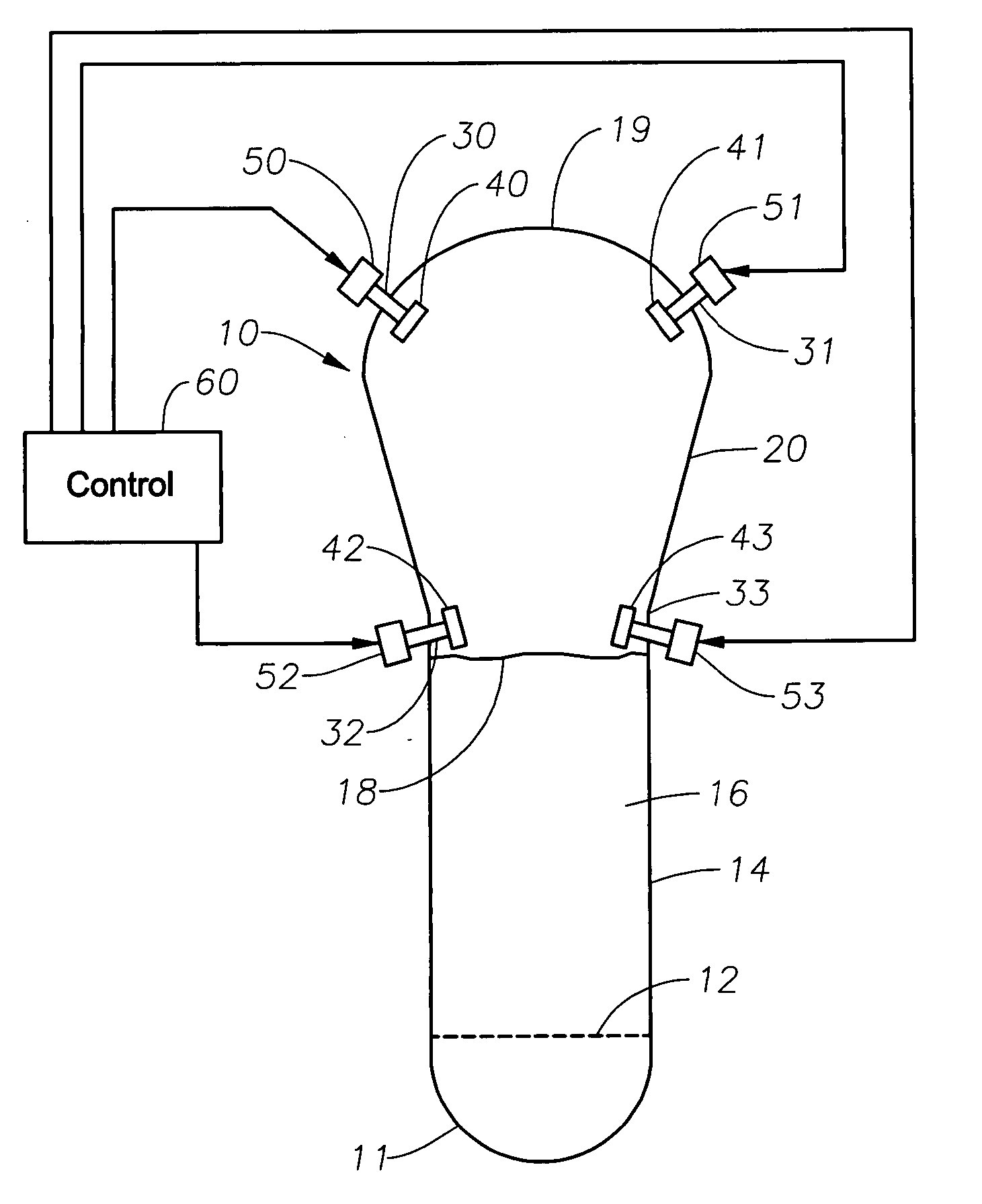
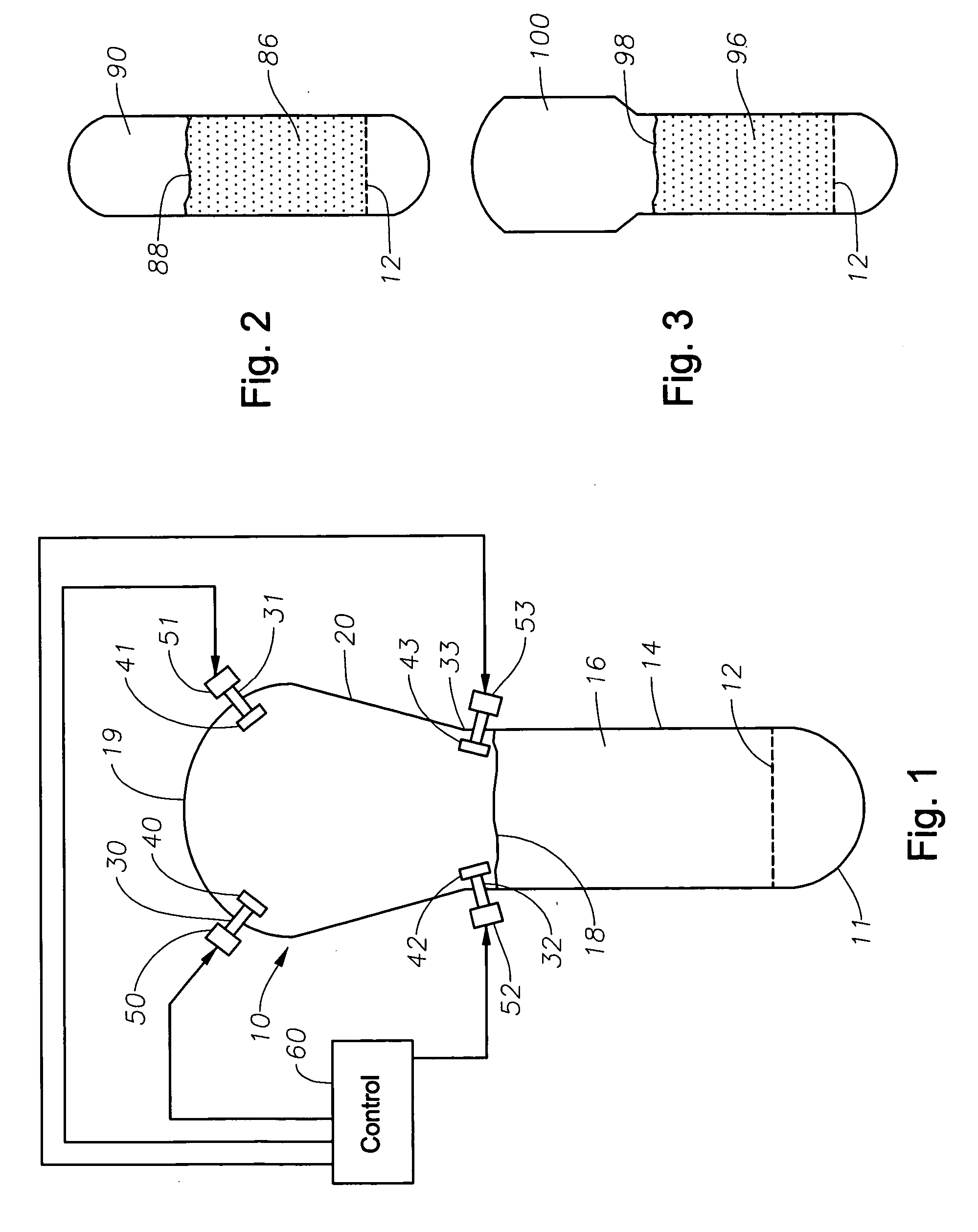
[0035] An embodiment of the inventive reactor system will be described with reference to FIG. 1. The FIG. 1 system includes fluidized bed reactor 10. Reactor 10 has a bottom end 11, a top section 19, a cylindrical (straight) section 14 between bottom end 11 and top section 19, and a distributor plate 12 within section 14. The diameter of each horizontal cross-section of section 19 is greater than the diameter of straight section 14. In operation, dense-phase surface 18 is the boundary between lean phase portion present within reactor 10 (above dense-phase surface 18) and dense-phase portion 16 within reactor 10 (in the volume bounded by section 14, plate 12, and surface 18). In operation, freeboard surface 20 of reactor 10 includes the inner surface of top section 19 and the portion of the inner surface of section 14 above surface 18.

[0036] The FIG. 1 system also includes four sonic sources mounted in positions for cleaning reactor 10's freeboard surface 20. One sonic source includ...


PUM

PropertyMeasurementUnit
conical angleaaaaaaaaaa
angleaaaaaaaaaa

Abstract

In some embodiments, a method for sonically cleaning a reactor (for example, a fluidized bed reactor useful for the production of polyolefins) using a set of sonic sources, including by varying the operating mode of the set of sources to reduce or prevent cleaning problems that would otherwise result from weak spots if the operating mode were not so varied. Other embodiments are methods for determining positions and operating parameters (e.g., duty cycle and output acoustic wave frequency) of each source of a set of sonic sources to be used for sonically cleaning a reactor, and methods including the steps of determining a position (relative to a reactor) of each source of a set of sonic sources, positioning each said source in the determined position, and then sonically cleaning a surface of the reactor including by varying the operating mode of the set of sources to reduce or prevent cleaning problems that would otherwise result from weak spots if the operating mode were not so varied.

Description

CROSS-REFERENCE TO RELATED APPLICATION [0001] The present application claims priority to Provisional U.S. Patent Application U.S. Ser. No. 60 / 602,936 filed Aug. 19, 2004 and is herein incorporated by reference.FIELD OF THE INVENTION [0002] The invention pertains to methods for sonic cleaning of reactors (e.g., fluidized bed reactors useful for the production of polyolefins). Some embodiments of the invention pertain to operation of a set of sonic sources to clean a reactor with reduced or minimized acoustic wave cancellation, to reduce or eliminate the occurrence of weak spots (areas on the reactor surface where incident acoustic wave intensity is undesirably low). BACKGROUND OF THE INVENTION [0003] The expression “weak spot” herein denotes an area on the surface of a reactor undergoing sonic cleaning, at which incident acoustic wave intensity is undesirably low as a result of acoustic wave cancellation. For example, if acoustic waves from two or more sources propagate directly to a...

Claims


Application Information

Patent Timeline
Patent Type & Authority Applications(United States)
IPC IPC(8): B08B3/12B08B9/00
CPCB08B7/02B08B9/08C08F10/00C08F210/16C08F2/34C08F2/002C08F210/06C08F2500/12C08F210/14
Inventor CAI, PINGMATTHEWS, WILLIAM A.
Owner CAI PING
Learn More